During the construction of earth retaining structures, it is very common to excavate the area, construct the earth retaining structure, backfill with the recommended material, and compact.
Pressure is exerted on the walls of the retaining structure during compaction, and some pressure is locked back in the soil after the machine is removed (that is why compaction pressure is usually treated as a permanent action).
The pressure on a wall retaining a compacted backfill is usually in excess of the one predicted using classical theory. The typical pressure distribution due to compaction is shown in Figure 1 according to Ingold (1979). Compaction pressure will be maximum up to a depth hc, after which it is locked into the pressure from the retained material. Therefore, pressure distribution at the back of a compacted retaining wall is not essentially triangular (in the absence of ground water).
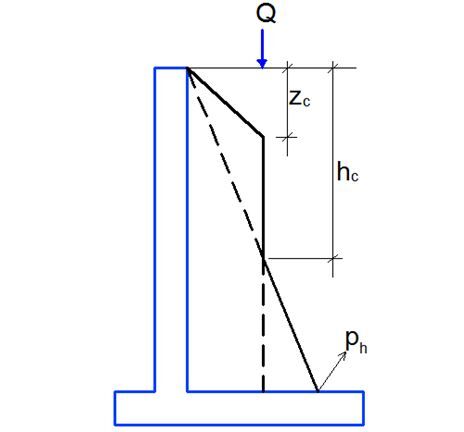
The simplified method for evaluating the compaction pressure at the back of a retaining wall is given by the equations below;
Maximum horizontal pressure induced by compaction = √(2Qdγk,f)/π)
Zc = k √(2Qd)/(πγk,f)
hc = 1/k √(2Qd)/(πγk,f)
ph = kγk,fz
Where;
k = pressure coefficient (For retaining walls which can move forward sufficiently to mobilise active condition in the fill, k = ka. For unyielding rigid structures, k = ko)
γk,f = characteristic value of the density of the fill material
ph = horizontal pressure from the overburden stress
Qd = γFQk
Where;
γF = partial factor and
Qk = characteristic design compaction force (see Table 1 below)
For dead weight roller compactors, the effective line load is the weight of the roller divided by its roll width, and for vibratory rollers it should be calculated using an equivalent weight equal to the dead weight of the roller plus the centrifugal force generated by the roller’s vibrating mechanism. The centrifugal force may be taken to be equal to the dead weight of the roller in the absence of trade data. Typical values for different compaction machines are given in Table 1.
Table 1: Design force of Different Compaction Machines (Nayaranan and Goodchild, 2012)
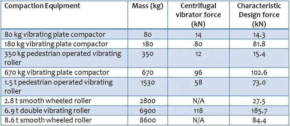
Using the values from Table 1, the compaction pressure expected from the compacting machine can be calculated and incorporated into the design calculation.
References
(1) Ingold, T S (1979): The effects of compaction on retaining walls. Geotechnique 29(3), pp 265-283
(2) Narayanan R. S. and Goodchild C. H. (2012): Concrete Basements: Guidance on the design and construction of in situ concrete basement structures, London, UK: MPA – The Concrete Centre




Many thanks Ubani