Piled raft foundations represent an economical and practical solution for situations where a conventional raft foundation falls short of design requirements. This type of foundation system strategically integrates a limited number of piles beneath the raft, allowing the raft itself to still contribute significantly to the load-bearing capacity.
This key distinction separates them from traditional pile foundations, where the primary responsibility for supporting the structure rests solely on the piles. Consequently, piled raft foundations occupy a unique position within the broader category of pile foundation systems, necessitating more complex analytical, design, and application considerations.
The piled raft foundation system itself comprises three key components:
- Piles: These deep foundation elements transfer heavy structural loads to deeper and more stable soil layers.
- Raft: This shallow foundation element distributes loads across its footprint, primarily utilizing the near-surface bearing capacity of the soil.
- Supporting Soil: This plays a critical role in transmitting loads from the structure to the foundation system.

By combining the capabilities of piles and rafts, the piled raft foundation system offers a synergistic solution for supporting heavy structures. It leverages the deep load-bearing capacity of piles while simultaneously utilizing the shallow load-carrying capacity of the raft. This combined approach effectively resists both vertical and lateral loads, ensuring the serviceability and stability of the structure.
Load-settlement behaviour within piled raft systems is influenced by a multitude of factors. The physical and mechanical properties of the soil, raft foundation, and pile foundation all play a significant role. Furthermore, the construction sequence of the building itself can also exert an influence. While a range of simplified, approximate, and advanced methods exist for analyzing this complex system, the most realistic results are typically obtained through the use of advanced finite element analysis.
Piled raft foundations have become a prominent choice for a wide range of demanding construction projects. Their versatility and ability to handle challenging soil conditions make them ideal for high-rise buildings in urban centers, where maximizing footprint usage is crucial. Landmark structures like the Burj Khalifa in Dubai and the Shanghai Tower in China employed piled raft foundations to ensure stability and support their immense weight.
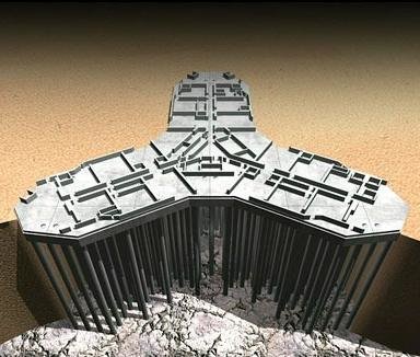
Piled rafts also find application in infrastructure projects such as offshore wind turbine installations, where they provide a stable base for these towering structures amidst wind and wave loads. Furthermore, their ability to resist buoyancy is valuable for projects on sites with high water tables, such as waterfront developments or structures built on reclaimed land.
Types of Piled Raft Foundation
Piled raft foundation can be broadly categorised into two;
- Piled raft for settlement control, and
- Piled raft for load transfer
Piled raft for settlement reduction
While raft foundations can offer adequate bearing capacity, they may still be susceptible to excessive settlement. Traditionally, this issue is addressed by incorporating a basement and a basement raft, which effectively reduces the total load acting on the foundation system. However, when this approach is not feasible, an alternative solution involves introducing a limited number of piles beneath the raft.
These piles function by transferring a portion of the overall load away from the raft itself. As the piles do not need to carry the entire load, the required number is significantly lower compared to a traditional piled foundation design. Additionally, due to this load redistribution, the settlement experienced by the raft is brought within acceptable limits.
Piled raft for load transfer
The second category of piled rafts, designated as “conventional,” finds application in scenarios where the underlying soil exhibits pronounced weakness and a high water table is present. In such conditions, the adoption of a raft foundation becomes essential.
These rafts serve a dual purpose: first, resisting the buoyant forces exerted by the groundwater, and second, transmitting all net structural loads to the piles for transfer to deeper, more competent soil layers. Consequently, the number of piles necessitated in this scenario will be considerably greater compared to the previous case described.
In essence, piled raft foundations offer a synergistic approach to foundation design, leveraging the strengths of both piles and rafts. The raft’s ability to share the load and reduce differential settlements, coupled with the piles’ capacity to act as “stress reducers” and “settlement reducers” while enhancing the overall bearing capacity, paves the way for efficient and reliable foundation systems, particularly in challenging soil conditions.
Load Transfer and Sharing in Piled Raft Foundation
The load distribution in foundation systems plays a crucial role in determining the interaction between the structure and the underlying soil. While a footing or raft primarily affects the shallow soil layers (approximately 1-2 times its width), pile foundations transfer loads to deeper strata. Combining these two approaches in a combined Pile and Raft Foundation (CPRF) system creates a complex interplay influenced by several factors.
These factors include:
- The rigidity of the raft: A stiffer raft tends to distribute load more evenly across the foundation, while a flexible raft allows for greater load transfer to the piles.
- Soil properties: The stiffness and bearing capacity of the underlying soil layers significantly impact the load transfer mechanisms.
- Pile characteristics: The number, depth, and rigidity of the piles within the raft influence how the load is shared between the piles and the raft.
The piled raft foundation system, responsible for transferring a structure’s load to the underlying soil, presents a complex interaction that have captivated researchers for years. Early notions, often overly conservative, assumed that the raft, in direct contact with the soil, offered no resistance to applied loads.
However, recent research works challenge this assumption, highlighting the raft’s significant contribution, particularly in clayey soils subjected to substantial structural loads. These studies reveal that the raft bears a portion of the load, while the piles carry the remaining portion through a creep mechanism.
The analysis and design of piled raft foundations, therefore, demand careful consideration of various critical factors, including:
- Raft thickness and dimensions
- Pile length, diameter, and configuration within the raft
- Underlying soil properties
- Stiffness characteristics of both the pile and raft
These factors collectively influence the load-sharing mechanism between the piles and the raft, ultimately impacting the stability and serviceability of the structure.
Furthermore, the success of piled raft foundation hinges on understanding the two key interaction types:
- Pile-to-pile interaction: This interaction depends heavily on the soil’s elastic modulus, the pile slenderness ratio (s/d), and the pile length. Ignoring this interaction can lead to underestimating settlements and bending moments in the raft, compromising structural safety.
- Pile-to-raft interaction: This interaction influences the load distribution between the piles and the raft, affecting the overall settlement behaviour of the foundation system.
Nevertheless, combined pile and raft foundation systems have challenged researchers for years due to the complexities associated with load-sharing and analysis. Several researchers have endeavoured to address this challenge, notably, by proposing simplified methods that incorporate various simplifications. However, these methods should be employed with caution due to their inherent limitations.
Quantifying the load contribution of each element within a piled raft system remains a topic of ongoing investigation. While some researchers suggest piles carry 50-80% of the total load, others provide a wider range of 30-60% for the raft’s contribution, emphasizing the dependence on factors like soil conditions, pile length, and spacing. Their research also highlights a decreasing raft contribution with denser pile spacing and increased pile length.
Further research strengthens the argument for the raft’s significant role, attributing up to 50% of the structural load to its contribution.
Classical Methods of Detemining Pile-Raft Load
Some classical methods of detemining pile-raft load sharing are discussed below.
Randolph Method
In the method proposed by Randolph (1994), load sharing ratio between pile group and pile raft, pile raft stiffness and settlement of piled raft can be calculated by using Eq. 1 to Eq. 4.
α = QR/QPG = 0.2/[(1 – 0.8(KR/KPG)] × KR/KPG ——— (1)
β = QR/QPG = 1/(1 + α) ——— (2)
KPR = [1 – 0.6(KR/KPG)]/[1 – 0.64(KR/KPG)] × KPG ——— (3)
S = Q/KPR ——— (4)
Where,
α = Load sharing ratio between raft and pile group,
β = Load sharing ratio between pile group and pile raft,
KR = Stiffness of the raft
KPG = stiffness of the pile group
KPR = stiffness of the piled raft
S = Settlement of piled raft,
Q = Design load
Poulos-Davis-Randolph (PDR) Method
In the method proposed by Poulos, Davis, and Randolph, load sharing ratio between raft and piled raft (X) can be determined using Randolph (1994) method and piled raft settlement (S) can be established using Poulos and Davis (1980) method.
X = Qr/Qpr = [(1 – αrp)kr]/[kpg + (1 – 2αrp)kr] ——— (5)
S = Qpr/kpr ——— (6)
kpr = [kpg + (1 – 2αrp)kr]/[1 – αrp2 (kr/kpg)] ——— (7)
αrp = 1 – [In(rc/r)/ς] ——— (8)
rc = √(A/nπ) ——— (9)
ς = In(rm/r) ——— (10)
rm = {0.25 + ξ[2.5ρ(1 – v) – 0.25]}L ——— (11)
ρ = Gavg/Gl ——— (12)
ξ = Gl/Gb ——— (13)
where;
Qr = Load carried by the raft
Qpr = Load carried by piled raft,
kr = stiffness of the raft
kpg = stiffness of the pile group
kpr = Stiffness of the piled raft,
αrp = Interaction factor,
A = Raft area,
n = Number of piles
L = length of piles
rm = Maximum radius from pile axis,
Gl = Shear modulus of soil along pile shaft
Gb = Shear modulus of soil at pile end
ν = Poisson’s ratio of soil.
Design of Piled Raft
According to Poulos (2001), the design of a piled raft foundation can be effectively divided into three distinct stages. The initial stage focuses on a preliminary analysis, estimating the impact of varying pile numbers on the overall load capacity and settlement of the structure. This analysis is typically approximate in nature.
Additionally, preliminary design stages often benefit from incorporating load-sharing ratios and settlement values derived from empirical studies and case histories. The expertise of designers familiar with piled raft systems remains an important component in achieving optimal outcomes.
The second stage goes deeper, aiming to identify the specific locations where piles are necessary and providing an initial indication of the required piling specifications.
Finally, the third stage represents the detailed design phase. Here, a more refined analysis is employed to confirm the optimal number and positioning of the piles. Additionally, this stage gathers crucial information for the structural design of the entire foundation system.
Complexities inherent to piled raft systems necessitate the use of sophisticated analytical methods during the design stage. These methods, such as the finite element method (FEM), boundary element method (BEM), equivalent element method (EEM), and plate-on-spring method (POSM), account for the numerous variables influencing the system’s behaviour.
Approximate methods like the “strip on springs” approach and the “plate on springs” offer further avenues for analysis. These methods offer simplified representations of the raft and piles (as springs) to understand their interaction.
For more detailed analysis, researchers recommend resorting to numerical methods, with the Finite Element Method (FEM) being the most prevalent choice. Software like SAP2000 and PLAXIS 3D foundation are prime examples of FEM-based solutions. FEM provides approximate solutions for various nonlinear engineering problems, including those encountered in combined piled raft foundation analysis.
It is important to note that while simplified methods can provide reasonable results for preliminary assessments, numerical methods like FEM offer a superior level of accuracy and detail for complex piled raft foundation systems. Recognizing the limitations of each approach is paramount for selecting the most appropriate analytical tool for a specific project.
Summarily, understanding the load-sharing mechanisms within piled raft foundation remains a dynamic field of research. While simplified methods offer initial insights, numerical methods like FEM provide a more robust and accurate means for analyzing these complex foundation systems. Choosing the appropriate analytical approach requires careful consideration of the project’s specific needs and complexities.
Preliminary Design Example of Piled Raft Foundation System
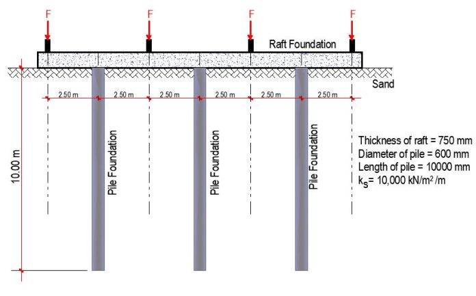
This section considers the preliminary design of a proposed piled raft foundation system. The raft is 750 mm thick and the superstructure load distribution on the raft is shown in Fgure 3. The initial proposed distribution of the piles, comprising of 9 number of 600 mm diameter piles is shown in Figure 4.


Thickness of raft = 750 mm
Modulus of subgrade reaction ks = 10000 kN/m2/m
Modulus of horizontal compressibility nh (medium dense wet sand) = 4000 kN/m2/m
Pile diameter = 600 mm
Depth of pile = 10 m
Horizontal modulus of subgrade reaction = nh(z/d) ——— (14)
The horizontal modulus of subgrade reaction was used in modelling the piles, and the spring stiffness varied with depth according to equation (14).
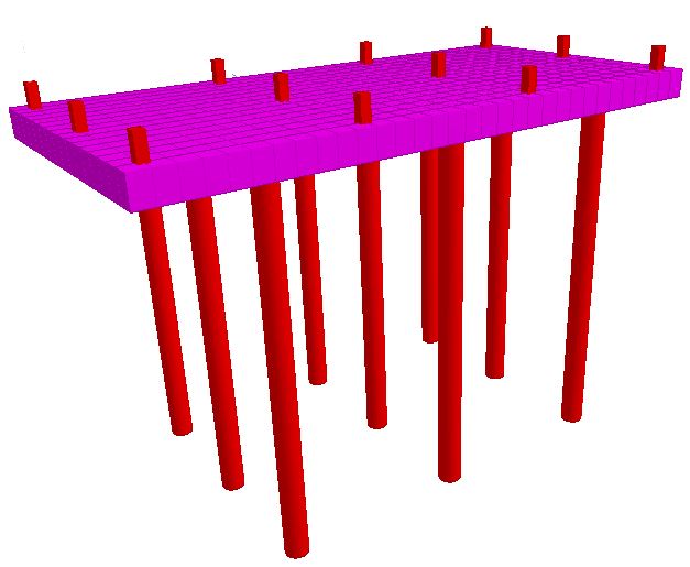


Total load applied on the foundation = 4(350) + 2(500) + 6(600) = 6000 kN
From the analysis results,
Total load transferred to the piles = 900 kN
Therefore, total load resisted by the raft = 6000 – 900 = 5100 kN
In this case, about 85% of the load is resisted by the raft foundation. If it is a piled raft foundation where the piles are to be used in load transfer, the arrangement of the piles will have to be changed. However, if it is a system where the piles are to be used for settlement control, the pile arrangement can be evaluated for acceptance or rejection.
In a different scenario when the number of piles was increased to 18 (additional piles were introduced along the column gridlines), 69% of the load was resisted by the raft. Therefore, preliminary analysis requires a careful consideration of the location and number of piles in the system.
Conclusion
Piled raft foundation systems offer a powerful solution for navigating complex soil conditions and supporting substantial loads. The design process involves a meticulous three-stage approach, starting with a preliminary analysis, then progressing to detailed location and quantity determination of piles, and finally culminating in a refined analysis for optimal pile placement and structural design of the entire foundation.
This staged approach ensures an efficient and cost-effective foundation that leverages the strengths of both raft foundations and pile foundations. Piled raft systems are a versatile solution for high-rise buildings, infrastructure projects, and construction on challenging sites, providing the stability and support necessary for a wide range of demanding applications.
Sources and Citations
Randolph M. F. (1994). Design methods for pile groups and piled rafts, 13th ICSMFE, New Delhi, India, 61-82.
Poulos H.G. and Davis E.H. (1980). Pile foundation analysis and design, John Willey and Sons, New York, USA.
Poulos H.G. (2001). Piled raft foundations: designs and applications. Geotechnique 51(2):95-113





Good