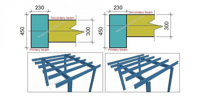
In some cases, structural members are not perfectly connected to each other along their centroidal axis. This can be as a result of structural arrangement, construction specifications, or feasibility of execution. There are provisions on Staad Pro software to offset beam members in order to reflect as closely as possible the real structural arrangement. In this article, we are going to show how you can offset beams on Staad Pro.
Step 1: Do a little calculation
You should know the value through which you wish to offset on structural member from the other. A little but simple calculation is required in order to know the value to input into staad Pro. Let us assume that a primary beam of 450 mm depth is supporting a secondary beam of 300 mm depth. By default, Staad will join the beams along their centrelines as shown in Figure 1.
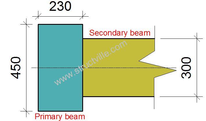
Let us assume that you want the top fibre of the primary and secondary beams to flush, you will notice that the secondary beam will need to move up by (450/2) – (300/2) = +75 mm. Note that the same effect will be achieved if the primary beam comes down by -75mm.
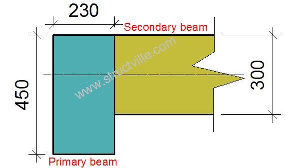
Also, if we want to the secondary beam to rest on top of the primary beam, then the secondary beam will need to move up by (75 mm + 300 mm = 375 mm). Note that additional internal stresses will be induced in the members due to the eccentricities in the connection.
Step 2: Input your values
After modelling your structure, go to GENERAL → SPEC → BEAM → OFFSET
Depending on the arrangement of the structure, you can offset in any direction you wish at the start and end of each member. Assign the the command to the beam in question.
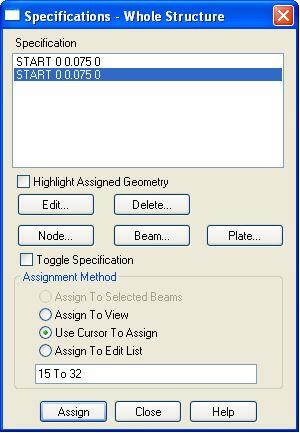
Step 3: Load the structure and analyse as usual
You can now apply the loading on the structure, and analyse as appropriate.
Watch a sample video tutorial below;

