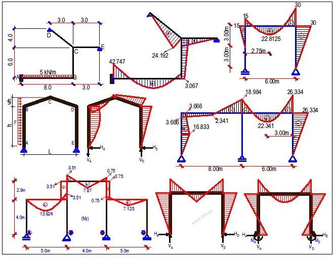
In the field of structural engineering, understanding the internal forces acting on framed structures is important for the design of such structures. Among these forces, bending moment plays a very important role in influencing the behaviour of beams and columns in framed structures under various loading conditions. This article discusses the concept of bending moment and its visualization through bending moment diagrams (BMDs) for framed structures.
Understanding Bending Moment
Imagine a beam supported at its ends and subjected to a transverse load (a load acting perpendicular to the beam’s axis). This load induces internal forces within the beam, causing it to bend. The bending moment at any point along the beam’s length represents the turning effect (rotational tendency) or moment created by the internal forces acting on that specific section. It is essentially the product of the force (F) acting at a perpendicular distance (d) from the point of interest, expressed mathematically as:
M = F × d
The bending moment tends to rotate the beam section about an axis perpendicular to its longitudinal axis. A positive bending moment signifies concavity downwards while a negative bending moment indicates concavity upwards.
Bending Moment Diagrams
A bending moment diagram (BMD) is a graphical representation of the bending moment throughout the length of a beam or a member in a framed structure. This diagram helps visualize the variation of the bending moment along the member, enabling engineers to identify critical sections where the moment is highest and assess the potential for bending failure. Bending moment diagrams are plotted in the tension zone of structures.
With the advent of numerous structural analysis and design software, bending moment diagrams can easily be generated using results from finite element analysis.
Steps to Construct a Bending Moment Diagram
- Determine the support reactions: This involves analyzing the entire frame to calculate the forces acting at the supports due to the applied loads. For statically determinate frames, the equations of equilibrium are sufficient for determining the support reactions but for statically indeterminate structures, methods like the force method can be used.
- Cut the member: Imagine isolating a specific section of the member by making a virtual cut at a chosen point.
- Treat the section as a free body: Draw a free-body diagram of the isolated section, including all external forces (support reactions and applied loads) acting on it.
- Apply equilibrium equations: Utilize the principles of equilibrium (summation of forces and moments equal to zero) to solve for the internal shear force (V) and bending moment (M) at the cut section.
- Repeat for different sections: Choose multiple points along the member’s length and repeat steps 2-4 to determine the shear force and bending moment at each point.
- Plot the values: Plot the calculated bending moments on the vertical axis and the member’s length on the horizontal axis, connecting the points to form a smooth curve. This curve represents the bending moment diagram for the member.
Interpreting Bending Moment Diagrams
Bending moment diagrams reveal valuable information about the bending behaviour of a framed structure:
- Zero bending moment: Points on the BMD where the curve crosses the horizontal axis indicate locations where the bending moment is zero. These points typically occur at supports or points of contraflexure.
- Maximum and minimum bending moment: The peak positive and negative values on the BMD represent the sections experiencing the highest and lowest bending moments, respectively. These sections are often critical for design considerations.
- Slope of the BMD: The slope of the BMD at any point signifies the rate of change of the bending moment. A positive slope indicates an increasing moment, while a negative slope represents a decreasing moment.
Applications of Bending Moment Diagrams
Bending moment diagrams are instrumental in various aspects of structural engineering, including:
- Structural design: They aid in selecting appropriate beam sizes and materials by identifying sections with high bending moments, ensuring sufficient strength and preventing failure.
- Deflection analysis: By knowing the bending moment distribution, engineers can estimate the deflection of the frame using various methods, evaluating its serviceability under load.
- Reinforcement detailing: In reinforced concrete structures, BMDs guide the placement of steel reinforcement to counteract the bending moment and ensure adequate structural capacity.
Typical Bending Moment Diagrams for Rigid Frames

F = Total Load
IAB = ICD (the moment of inertia of the columns are equal)
K =IBCh/IABL
k1 = K + 2
k2 = 6K + 1
k3 = 2K + 3
k4 = 3K + 1
Rigid frame subjected to gravity uniformly distributed load on the beam
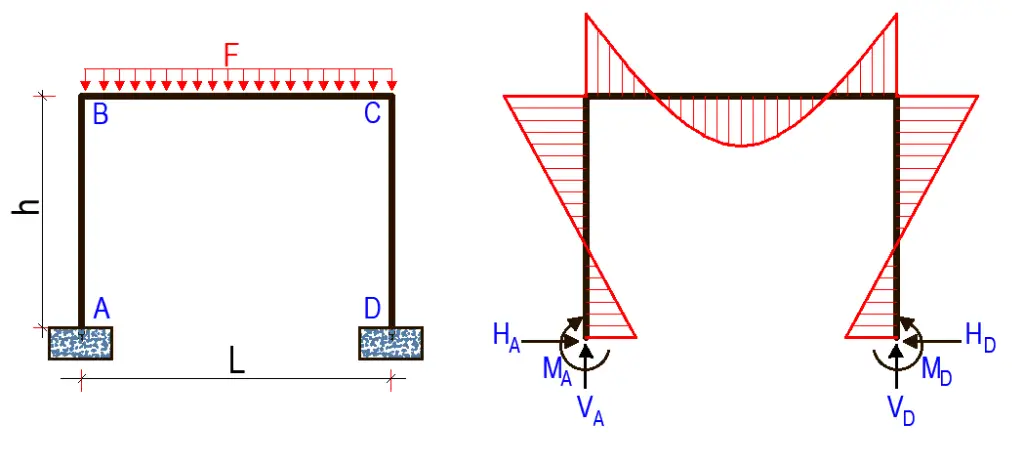
FOR FIXED SUPPORTS
HA = HD = Fl/4hk1
VA = VD = F/2
MA = MD = Fl/12k1
MB = MC = Fl/6k1
FOR PINNED SUPPORTS
HA = HD = Fl/4hk3
VA = VD = F/2
MA = MD = 0
MB = MC = HAh = Fl/4k3
Rigid frame subjected to a point load on the beam

FOR FIXED SUPPORTS
HA = HD = 3Fl/8hk1
VA = VD = F/2
MA = MD = Fl/8k1
MB = MC = Fl/4k1
FOR PINNED SUPPORTS
HA = HD = 3Fl/8hk3
VA = VD = F/2
MA = MD = 0
MB = MC = HAh = 3Fl/8k3
Rigid frame subjected to a horizontal uniformly distributed load on the column
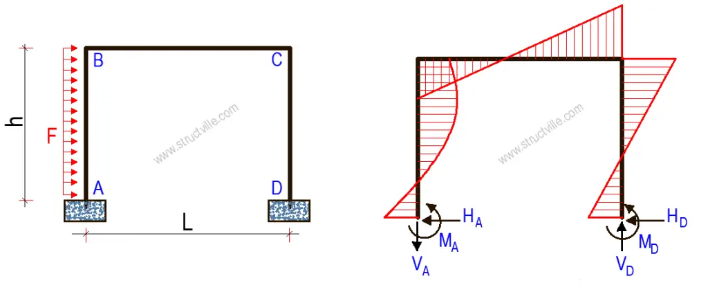
FOR FIXED SUPPORTS
HA = F - HD
HD = Fk3/8k1
VA = -FhK/lk2 = -VB
MA = Fh/4[(K + 3)/6k1 + (4K + 1)/k2]
MB = h(HA - ½F) - MA
MC = HDh - MD
MD = Fh/4[(K + 3)/6k1 - (4K + 1)/k2]
FOR PINNED SUPPORTS
HA = F/8[(6k3 - K)/k3]
HD = F - HA
VD = -VA = Fh/2l
MA = MD = 0
MB = h(½F - HD) = 3Fhk1/8k3
MC = HDh = Fh/8[(2k3 + K)/k3]
Rigid frame subjected to a horizontal point load at the top
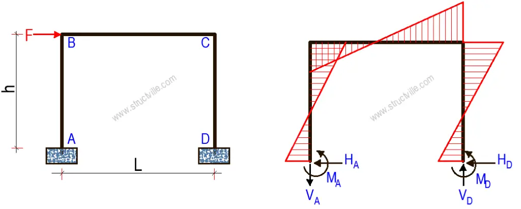
FOR FIXED SUPPORTS
HA = HD = F/2
VA = -VD = -3FhK/Lk2
MA = MD = Fhk4/2k2
MB = MC = 3FhK/2k2
FOR PINNED SUPPORTS
HA = HD = F/2
VD = -VA = Fh/l
MA = MD = 0
MB = MC = Fh/2
Conclusion
Understanding bending moments and their visualization through bending moment diagrams is fundamental for structural engineers. By mastering this concept, engineers can effectively analyze framed structures, optimize designs, and ensure the safety and serviceability of their creations under various loading conditions.

