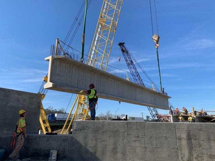
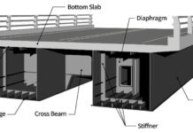
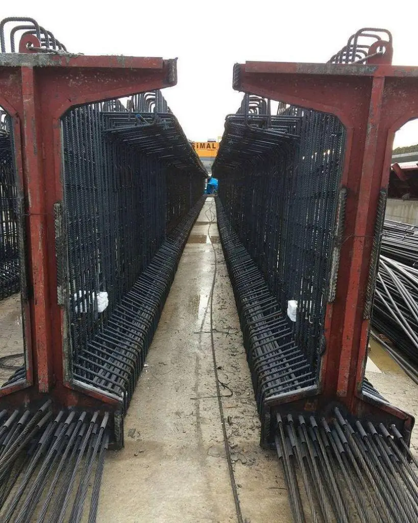
A precast prestressed girder is an alternative economical solution to the construction of long-span bridges. This solution allows for quick bridge construction by using girders that are fabricated off-site, transported to the job site, and then installed into place.
In a construction site where efficiency or minimal traffic interruption is necessary, prestressed bridge girders are recommended because they require little to no falsework. Prestressed girders are very cost-effective and can be used for spans of up to 50 metres (166 ft).
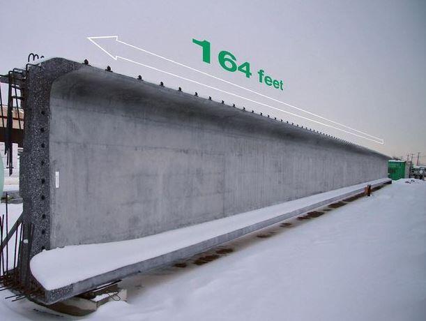
In prestressed concrete design, structures are generally designed at the serviceability limit state (SLS). However, it is equally important to ensure that the designed structure has the sufficient moment and shear capacity at the ultimate limit state (ULS). In this article, checking for bending capacity at the ULS is discussed.
In order to determine the ultimate moment capacity of a given section which has been designed to the serviceability limit state of bending, it is necessary to determine the position of the neutral axis at the ultimate limit state. This usually involves a trial-and-error calculation procedure.
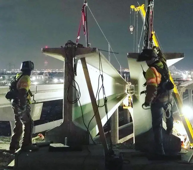
Initially, a value for the neutral axis depth x is assumed. For the assumed depth, compressive forces in various parts of concrete and tensile force in all steel reinforcement are calculated. For equilibrium, the algebraic sum of total tensile and compressive forces must be zero. If the sum is not zero, calculations are repeated for a new value of neural axis depth and the calculations are continued till the correct value of x is found.
Ultimate Bending Strength Calculation of a Prestressed Girder
Calculate the ultimate bending strength of a bridge beam girder shown below. The calculation is adapted from Bhatt (2011).
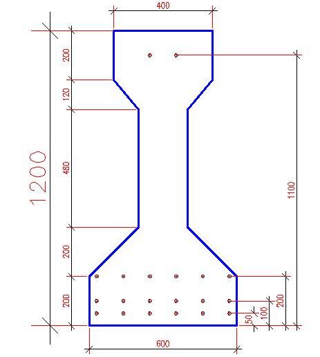
The details of material properties, prestress details, etc. are follows.
Concrete: Concrete grade 40/50, fck = 40 MPa, material safety factor, γm = 1.50, fcd = fck/γm = 26.7 MPa
Using a rectangular stress block: λ = 0.8, η = 1.0, fck ≤ 50 MPa, ηfcd = 26.7 MPa
Maximum strain in compression εcu3 = 3.5 × 10⁻³; σc ≤ 50 MPa
Steel: 12.7 mm nominal diameter 7-wire strand with an effective cross-sectional area of 112 mm2.
fpk = 1860 MPa, fp0.1k ≈ 0.88 × fpk = 1637 MPa, γm = 1.15
fpd = fp0.1k /γm = 1424 MPa, Es = 195 GPa
Prestressing details: 20 strands are located at the following distances from the soffit: six each at 50, 100 and 200 mm and two at 1100 mm from the soffit. The cables are spaced horizontally at 50 mm c/c.
Total prestress at service Ps = 2037 kN
Stress σpe due to prestress force in the strand = Ps/Area of 20 stressed strands = 2037 × 103/ (20 × 112) = 909 MPa
Prestrain εpe = σpe/Es = 909 / (195 × 103) = 4.66 × 10⁻³
The calculations consist of the following steps.
Step 1: Estimate a value for neutral axis depth:
i. Total tensile force:
Assume all 18 strands in the bottom three rows only ‘yield’ i.e. stress is a maximum of fpd equal to 1424 MPa. The area of each strand = 112 mm2.
Therefore total tensile force T = 18 × 112 × 1424 × 10-3 = 2871 kN
ii. Total compressive force:
Assuming a rectangular stress block, the uniform compressive stress = ηfcd = 26.7 MPa, λ = 0.8
(a). Total compressive force in top flange = 26.7 × 200 × 400 × 10-3 = 2136 kN
(b). Total compressive force in the top trapezium = 26.7 × 0.5 × (200 + 400) × 120 × 10-3 = 961.2 kN
Total compressive force C = 2136 + 961.2 = 3097.2 kN
C > T. Therefore stress block λx < (200 + 120) or x < 400 mm
Step 2: For an assumed value of neutral axis depth x, calculate the total tensile and compressive forces and check for equilibrium.
Iteration 1: Assume x = 350 mm.
Rectangular stress block depth s = λx = 0.8 × 350 = 280 mm.
The uniform compressive stress = ηfcd = 26.7 MPa
ii. Total compressive force:
(a) Compressive force in top flange = 2136.0 kN
(b) Total compressive force in part of the trapezium:
Depth dx of stress block inside the trapezium = s – depth of top flange = 280 – 200 = 80 mm
Width Bx of the trapezium at the bottom edge of the stress block:
Bx = width of web + (width of top flange – width of web) × (1 − dx /depth of trapezium)
Bx = 200 + (400 – 200) × (1− 80/120) = 267 mm
Compressive force in the trapezium = 26.7 × 0.5 × (400 + 267) × 80 × 10-3 = 712.4 kN
Total compressive force C = 2136.0 + 712.4 = 2848.4 kN
iii. Total tensile force:
Bending strain εb in strand at d from the compression face = εcu3 × (d – x)/x
Calculations are shown in the Table below.
| Distance from soffit (mm) | d (mm) | εb × 103 | εs = (εb + εpe) × 103 | σs, MPa | No. of strands | T (kN) |
| 50 | 1150 | 8.0 | 12.66 | 1424 | 6 | 957 |
| 100 | 1100 | 7.5 | 12.16 | 1424 | 6 | 957 |
| 200 | 1000 | 6.5 | 11.16 | 1424 | 6 | 957 |
| 1100 | 100 | -2.5 | 2.16 | 421 | 2 | 94 |
| Total | 20 | 2965 |
T = 2965.3 kN
The difference between the total tensile force and compressive force = 2965 – 2848 = 117 kN
The compressive force is too small, indicating that the neutral axis depth is larger than 350 mm.
Step 3: Assume x = 450 mm. Stress block depth s = λx = 0.8 × 450 = 360 mm
Iteration 2:
ii. Total compressive force:
(a). Total compressive force in top flange = 26.7 × 200 × 400 × 10-3 = 2136 kN
(b). Total compressive force in the top trapezium:
Depth dx of stress block inside the trapezium = s – depth of top flange = 360 – 200 = 160 mm > 120 mm
The entire trapezium is in compression.
Compressive force in the trapezium = 26.7 × 0.5 × (400 + 200) × 120 × 10-3 = 961.2 kN
(c). Compressive force in the web:
Depth of web in compression = s – 200 – 120 = 40 mm
Compressive force in web = 26.7 × 40 × 200 × 10-3 = 213.6 kN
Total compressive force C = 2136.0 + 961.2 + 213.6 = 3310.8 kN
iii. Total tensile force:
Bending strain εb in strand at d from the compression face = εcu3 × (d – x)/x
Calculations are shown in the Table below.
| Distance from soffit (mm) | d (mm) | εb × 103 | εs = (εb + εpe) × 103 | σs, MPa | No. of strands | T (kN) |
| 50 | 1150 | 5.44 | 10.10 | 1424 | 6 | 957 |
| 100 | 1100 | 5.06 | 9.72 | 1424 | 6 | 957 |
| 200 | 1000 | 4.28 | 8.94 | 1424 | 6 | 957 |
| 1100 | 100 | -2.72 | 1.94 | 378.0 | 2 | 85 |
| Total | 20 | 2956 |
T = 2955.6 kN
The difference between the total tensile force and compressive force
= 2956 – 3311 = −355 kN
Step 4: Interpolation
From the two values of x and the corresponding difference between the total tensile and compressive forces, the value of x for which the difference is zero can be determined by linear interpolation.
| x | T – C |
| 350 | 117 |
| 450 | -355 |
x = 350 + (450 – 350) × 117/ [117 − (− 355)] = 375 mm
Step 5: Final calculation
Assume x = 375 mm.
Stress block depth s = λx = 0.8 × 375 = 300 mm
ii. Total compressive force:
(a). Total compressive force in top flange = 26.7 × 200 × 400 × 10-3 = 2136 kN
(b). Total compressive force in the top trapezium:
Depth dx of stress block inside the trapezium = s – depth of top flange = 300 – 200 = 100 mm < 120 mm
Width Bx of the trapezium at the bottom edge of stress block = width of web + (width of top flange – width of web) × (1−dx /depth of trapezium) = 200 + (400 – 200) × (1 − 100 /120) = 233 mm
Compressive force in the trapezium = 26.7 × 0.5 × (400 + 233) × 100 × 10-3 = 845.5 kN
Total compressive force C = 2136.0 + 845.5 = 2981.5 kN
iii. Total tensile force:
Calculations are shown in the Table below;
| Distance from soffit (mm) | d (mm) | εb × 103 | εs = (εb + εpe) × 103 | σs, MPa | No. of strands | T (kN) |
| 50 | 1150 | 7.23 | 11.89 | 1424 | 6 | 957 |
| 100 | 1100 | 6.77 | 11.43 | 1424 | 6 | 957 |
| 200 | 1000 | 5.83 | 10.49 | 1424 | 6 | 957 |
| 1100 | 100 | -2.57 | 2.09 | 408.0 | 2 | 91 |
| Total | 20 | 2962 |
T = 2962 kN
The difference between the total tensile force and compressive force
= 2962 – 2982 = −20 kN
This is small enough to be ignored. In fact the correct value of x = 372 mm. The ‘error’ is because of linear interpolation.
Step 6:
Ultimate moment: The ultimate moment is obtained by calculating the moment of all forces, tensile as well as compressive about the soffit.
(a). Compressive force in top flange = 2136 kN
Lever arm from the soffit = 1200 – 200/2 = 1100 mm
(b). Compressive force in the top trapezium = 845.5 kN
Depth of stress block inside the trapezium dx = 100 mm
Width of the trapezium at the bottom edge of stress block Bx = 233 mm
Lever arm = 1200 – 200 – (dx/3) × [1 + Bx / (400 + Bx)] = 954 mm
iii. Tensile force forces at various level act at their position from the soffit as shown in the Table above.
The ultimate bending moment Mu is given by
Mu = [(2136 × 1100) + (845.5 × 954) – (957 × 50) – (957 × 100) − (957 × 200) – (91.4 × 1100)] × 10-3 = 2721.1 kNm
Calculation adapted from:
Bhatt P. (2011): Prestressed Concrete design to Eurocodes. Spon Press, Taylor and Francis. ISBN: 978-0-203-84725-1

