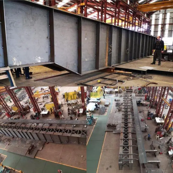
Plate girders are built-up beam sections manufactured to support massive vertical loads over long spans with consequent bending moments that are greater than the moment resistance of readily accessible rolled sections. The plate girder is a built-up beam that is made up of two flange plates that are fillet welded to a web plate to create an I-section (see Figure 1).
The primary function of the top and bottom flange of plate girders is to withstand the axial compressive and tensile forces induced by the applied bending moments, while the primary function of the web is to withstand shear. In fact, some codes of practice employ this division of structural action as the basis for design.

By extending the distance between them, the required flange areas for a given bending moment can be decreased in a plate girder. Therefore, it is advantageous to increase the distance between flanges for an economical design. The web thickness should be decreased as the depth increases to minimize the girder’s self-weight, however, this makes plate girders more susceptible to web buckling issues than rolled beam sections.
Plate girders are frequently employed in small- to medium-span bridges and occasionally utilized in buildings as transfer beams. Design guidelines are in BS EN 1993-1-5 (2006). This article describes current plate girder design procedures and includes references to the pertinent code provisions.

Advantages and Disadvantages of Plate Girders
Plate girder fabrication prices have decreased significantly as a result of the advent of highly automated workshops, but box girder and truss fabrication costs are still high because these structures must still be made largely by hand.
When compared to rolled sections, fabricated plate girders can make better use of the material since the designer has more ability to alter the section to account for variations in the applied forces. As a result, plate girders with variable depth have become more prevalent in recent years.
Compared to trusses, plate girders are more aesthetically beautiful and easier to transport and build than box girders.
The use of plate girders has some limitations. They are heavier, more difficult to transport and have higher wind resistance than trusses. It is also more challenging to provide openings for building services. Because compression flange stability is an issue, plate girder erection can occasionally present challenges.
Selection of cross-section for plate girders
During the preliminary design of plate girders, some factors can be considered for the initial selection of the dimensions. They are described as follows;
Span-to-depth ratios
Modern fabrication techniques enable the cost-effective production of plate girders with constant or variable depth. Constant-depth girders have historically been more prevalent in buildings, but as designers show a greater willingness to alter the steel structure to accommodate services, this could change. Table 1 lists suggested ratios of span to depth for plate girders in buildings.
| Applications | Span-to-depth ratio |
| (1) Constant-depth beams used in simply-supported composite girders, 12 to 20 and for simply-supported non-composite girders with concrete decking | 12 – 20 |
| (2) Constant-depth beams used in continuous non-composite girders using concrete decking (N.B. continuous composite girders are uncommon in buildings) | 15 – 20 |
| (3) Simply-supported crane girders (non-composite construction is usual) | 10 – 15 |
Recommended plate thickness and proportions
Although more slender cross-sections are permissible, in general, the slenderness of plate girders used in buildings should not exceed the restrictions established for Class 3 cross-sections (given in Clause 5.5 of BS EN 1993-1-1). The choice of plate thickness and cross-sectional buckling are connected. In order to restore proper stiffness and strength, if the plates are too thin, stiffening may be necessary; however, this additional labour is expensive.
In view of the above, the maximum depth-to-thickness ratio of the webs (cw/tw) of plate girders in buildings is usually limited to:
cw/tw < 124ε = 124(235/fyw)0.5
where fyw is the yield strength of the web plate.
The outstand width-to-thickness ratio of the compression flange (cf/tf) is typically limited to;
cf/tf < 14ε = 14(235/fyf)0.5
where fyf is the yield strength of the compression flange. Note that cw and cf are the flat element widths, measured from the edges of the fillet welds (or root radii for rolled sections).
For initial design purposes, when the weld size may be unknown, it is conservative to ignore the weld and take cw = hw (the distance between the flanges) for webs and cf = b/2 – tw/2 for outstand flanges. Changes in flange size along the girder are not usually worthwhile in buildings.
For non-composite girders the flange width is usually within the range 0.3 – 0.5 times the depth of the section (0.4 is most common). For simply-supported composite girders these guidelines can still be employed for preliminary sizing of compression flanges. The width of tension flanges can be increased by 30%.
Stiffeners
Plate girders used in structures don’t typically require longitudinal web stiffeners. When the resistance of the unstiffened web would otherwise be surpassed, transverse (vertical) web stiffeners may be used to increase the resistance to shear close to the supports or to carry highly concentrated transverse forces acting on the flanges. Because there is less shear in these areas, the necessity for intermediate stiffening reduces.
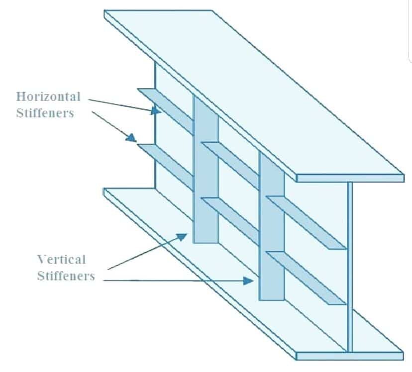
The use of intermediate transverse web stiffeners improves the web panels’ ultimate shear buckling strength τu (including post-buckling or post-critical), as well as elastic shear buckling strength τcr. A decrease in the web panel aspect ratio a/hw (width/depth) greatly enhances the elastic shear buckling strength.
Enhancing tension field action causes the boundary members to resist diagonal tensile membrane stresses that develop during the post-buckling phase, increasing the ultimate shear buckling strength (transverse stiffeners and flanges).
Since there is little gain in strength for smaller panel aspect ratios, intermediate transverse stiffeners are often positioned such that the web panel aspect ratio is between 1.0 and 2.0. In order to create what is known as a rigid end post, pairs of stiffeners are occasionally used at the end supports. Generally speaking, the girder’s overhang beyond the support is limited to no more than one-eighth of its depth.

