In bridge design, it is very necessary that bridge decks support both static and moving loads. Every component of a bridge needs to be designed to withstand the worst loading effect that could possibly arise in that part. In effect, traffic live loads should be placed where they will cause the most onerous effect on the structure. ‘Influence lines’ are a helpful tool for assessing the most severe loading condition.
An influence line represents the response of a specific element of a bridge to the effect of a moving load, such as reaction, shear force, bending moment, or axial force. It is a diagram where the value of the response at any point is equal to the effect caused by a unit load applied at that point. Influence lines provide a systematic approach for determining how the force, moment, or shear in a specific part of a structure changes as the applied load moves across the structure.
Influence lines for statically determinate structures consist of straight lines, but for indeterminate structures, they can have more complex shapes. The primary purpose of influence lines is to identify where to place live loads to achieve maximum effect.
Influence Lines for Shear in Simple Beams
Influence lines for shear at two sections of a simply supported beam are shown in Figure 1. When the summation of transverse forces to the left of a section is in the upward direction or when the summation of transverse forces to the right of the section are in the downward direction, positive shear is said to occur. For each position of the unit load, the shear force at sections 1-1 and 2-2 is determined by placing the unit force at various points.

The values provide the ordinate of the influence line, which may be used to draw the influence line diagrams for the shear force at sections 1-1 and 2-2. It should be noted that the slope of the influence line for shear on the left of the section is similar to the slope of the line on the right of the section. In other circumstances, this information can be used to draw the influence lines for shear force.
Influence Lines for Bending Moments in Simple Beams
Figure 2 shows the influence lines for the bending moment at the same sections, 1-1 and 2-2, of the simple beam under consideration in Figure 1. For a section, the moment is considered positive when the total of all the moments of the forces to the left is clockwise or when the sum to the right is counterclockwise. For various places of unit load, the values of the bending moment at sections 1-1 and 2-2 are obtained and plotted as shown in Figure 2.

It should be noted that a shear or bending moment diagram shows how shear or moment values change throughout the entire structure when loads are fixed in a specific position. Conversely, an influence line for shear or moment depicts how that response varies at a specific section of the structure due to the movement of a unit load from one end to the other. Influence lines are helpful in determining the magnitude of a specific response at the section where it is drawn, when the beam is subjected to various types of loading.
For instance, the shear force at section 1-1 is determined by the product of the load intensity, qo, and the net area under the influence line diagram assuming a uniform load of intensity qo per unit length operates throughout the full length of the basic beam depicted in Figure 22.
Since the net area at section 1-1 is 0.3P, the shear force there is 0.3qoP as well. The bending moment at the section is calculated from the area of the appropriate influence line diagram times the intensity of loading, qo. Therefore, the section’s bending moment is 0.08qoP2.
Solved Example
Let us consider the beam loaded as shown below. It is desirous to obtain the influence line for the support reactions, and for the internal stresses with respect to section 1-1.
In all cases, we will be taking P as unity (i.e 1.0)
(1) Influence line for support reactions
Support A
Support reaction at point A (FA) = (L – x)/L
At x = -L1;
FA = (L + L1)/L
At x = 0;
FA = 1.0
At x = L + L2;
FA = (L – L – L2)/L = – L2/L
Support B
Support reaction at point B (FB) = x/L
At x = -L1;
FB = -L1/L
At x = 0;
FB = 0
At x = L;
FB = 1.0
At x = L + L2;
FB = (L + L2)/L
(2) Influence line for bending moment with respect to section 1-1
(0 ≤ x ≤ a)
M1-1 = FA.a – P(a – x)
M1-1 = [P(L – x).a]/L – P(a – x)
But taking P = 1.0;
= [(L – x).a]/L – (a – x)
At x = -L1;
M1-1 = [(L + L1).a]/L – (a + L1) = [L1(a – L)/L] = -L1.b/L
At x = 0;
M1-1 = [(L – 0).a]/L – (a – 0) = [L1(a – L)/L] = 0
At x = a;
M1-1 = [(L – a).a]/L – (a – a) = [L1(a – L)/L] = a.b/L
(a ≤ x ≤ L)
M1-1 = [P(L – x)a]/L
At x = a;
M1-1 = [(L – a)a]/L = a.b/L
At x = L;
M1-1 = [(L – L)a]/L = 0
At x = L + L2;
M1-1 = [(L – L – L2)a]/L = – L2a/L
(2) Influence line for shear with respect to section 1-1
(0 ≤ x ≤ a)
Q1-1 = P(L – x)/L – P = – FB = –x/L
At x = -L1;
Q1-1 = L1/L
At x = 0;
Q1-1 = 0
At x = a;
Q1-1 = -a/L
(a ≤ x ≤ L)
Q1-1 = -(P.x)/L + P = (L – x)/L
At x = a;
Q1-1 = b/L
At x = L;
Q1-1 = 0
At x = L + L2;
Q1-1 = [(L – L – L2)]/L = -L2/L
Influence Lines for Trusses
Influence lines for support reactions and member forces can be constructed using the same approach as influence lines for various beam functions. They provide valuable information for determining the maximum load that can be applied to a truss. By analyzing the movement of a unit load across the truss, we can calculate the responses of interest at each panel point.
However, it is not necessary to calculate the member forces at every panel point, as certain parts of the influence lines can be identified as straight lines for multiple panels. Method of sections can be used to obtain the member forces in any panel of interest.


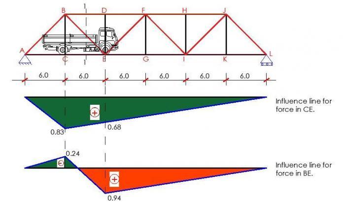
The truss shown above is used as an example to explain how to construct influence lines for trusses. Passing a section 1-1 and taking into account the equilibrium of the free body diagram of one of the truss segments yields the member forces in BD, CE, and BE.
First, a unit load is applied to node C, and the force in BD is calculated by calculating the moment about node E of all forces acting on the right-hand segment of the truss, then dividing that moment by the lever arm (the distance at which the force in BD is perpendicular to node E).
The resultant value provides the influence diagram’s ordinate at C in the truss. Similar to how the force in BD for a unit load imposed at E is represented by the obtained ordinate at E. Two additional points, one at each of the supports, can be added to the influence line to complete it. The relevant influence line diagram can be finished by obtaining the force in the member CE due to the unit load applied at C and E.
The influence line for force in BE can be obtained by taking into account the horizontal component of force in the diagonal of the panel. The influence diagrams for the member forces in BD, CE, and BE are shown in Figure 3. By running an imaginary vertical section through the panel and taking moments at the junction of the diagonal and the other chord, it is possible to estimate the influence line ordinates for the force in a chord member of a ‘curved-chord’ truss.
Qualitative influence lines: Müller–Breslau principle
One of the most effective methods of obtaining influence lines is by the use of the Müller–Breslau principle, which states that ‘the ordinates of the influence line for any response in a structure are equal to those of the deflection curve obtained by releasing the restraint corresponding to this response and introducing a corresponding unit displacement in the remaining structure’.
In this way, the shape of the influence lines for both statically determinate and indeterminate structures can be easily obtained, especially for beams.
Some methods for drawing influence lines are as follows:
Support reaction
Remove the support and introduce a unit displacement in the direction of the corresponding reaction to the remaining structure as shown in Figure 4 for a symmetrical overhang beam.

Shear
Make a cut at the section and introduce a unit relative translation (in the direction of positive shear) without relative rotation of the two ends at the section as shown in Figure 5.

Bending moment
Introduce a hinge at the section (releasing the bending moment) and apply bending (in the direction corresponding to positive moment) to produce a unit relative rotation of the two beam ends at the hinged section as shown in Figure 6.

Influence lines for continuous beams
Using the Muller–Breslau principle, the shape of the influence line of any response of a continuous beam can be sketched easily. One of the methods for beam deflection can then be used for determining the ordinates of the influence line at critical points.
Conclusion
In summary, influence lines are valuable tools in structural analysis, providing insights into the behaviour of structures under varying loads. They aid in determining critical locations, optimizing designs, evaluating load effects, and ensuring structural integrity. By utilizing influence lines, engineers can make informed decisions and design structures that are safe, efficient, and capable of withstanding the intended loads.
Reference
Shanmugam N. E. and Narayanan R. (2008). ‘Structural Analysis’ in ICE Manual of Bridge Engineering, Eds by Gerard Parke and Nigel Hewson. Thomas Telford Ltd, UK


