Structural stability is broadly defined as the capacity of a structure to recover equilibrium. As a topic in structural engineering, it is concerned with structural members that are subjected to external loading that induces compressive stresses in the body of the structure. Emphasis is on understanding the behavior of structures in terms of load displacement characteristics; on formulation of the governing equations; and on calculation of the critical load. An approach based on continuum method has been presented in this article for the evaluation of critical load of a ten-storey braced steel frame.
This is based on the work of Zalka (2013) and the assumptions in the analysis are as follows;
- The structure at least four storeys high with identical storey heights
- The frame is regular in the sense that their characteristics do not vary over the height
- Sway structures with built-in lower end at ground floor level and free upper end
- The floor slabs have great in-plane and small out-of-plane stiffness
- The deformations are small and the material of the structures is linearly elastic
- P-delta effects are negligible
- The frameworks are subjected to uniformly distributed vertical load at storey levels
- The critical load defines the bifurcation point
Analysis Example
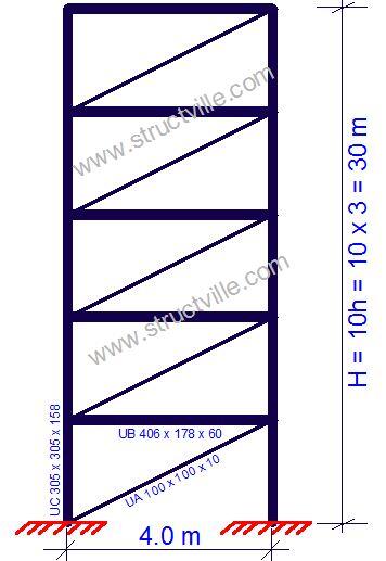
Calculate the critical load of the ten-storey steel frame work shown below. The height of each floor is 3m, and the properties of the members are given below. Take the modulus of elasticity of steel as 210,000 N/mm2.
Columns – UC 305 x 305 x 158 (Area = 201 cm2, Iyy = 38800 cm4)
Beams – UB 406 x 178 x 60 (Area = 76.5 cm2; Iyy = 21600 cm4)
Diagonal bracing = UA 100 x 100 x 10 (Area = 19.2 cm2; Iyy = 177 cm4)
The shear stiffness of the structure (for single braced frames) is shown below;

d = √(32 + 42) = 5 m
l = 4 m
h = 3 m
Ad = 19.2 cm2 = 19.2 x 10⁻⁴ m2
Ah = 76.5 cm2 = 76.5 x 10⁻⁴ m2
Eh = Ed = 210 x 106 kN/m2
K = {[53/(19.2 x 10-4 x 210 x 106 x 3 x 42)] + [4/(76.5 x 10-4 x 210 x 106 x 3)]}-1 = 137198.521 kN
The global second moment of area is;
Ig = ∑Ac,iti2 = 2 x (201 x 10-4 x 22) = 0.1608 m4
Load distribution factor rs is obtained from Table 1 as rs = 0.863.
Table 1: Load distribution factor rs as a function of n (the number of storeys) (Zalka, 2013)

The global bending critical load is;
Ng = (7.837rsEIg)/H2 = (7.837 x 0.863 x 210 x 106 x 0.1608)/302 = 253760.179 kN
As a function of βs = K/Ng = 137198.521/253760.179 = 0.541
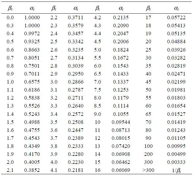
The critical load parameter αs is obtained by interpolating from the Table 2.
αs = 0.9
Table 2: Critical load parameter αs as a function of parameter βs (Zalka, 2013)
Finally, the critical load of the framework Ncr = αsK
Ncr = 0.9 x 137198.521 = 123485.25 kN
As a comparison, let us model the frame in Staad Pro software and carry out buckling analysis on the structure.
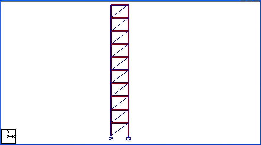
Based on the assumptions made in the analysis, the frame has been subjected to a load of 5 kN/m at each level. From the analysis result;
Total vertical load on the structure = 200 kN
Buckling amplification factor αs for Mode 1 = 687.439
Therefore, the critical buckling load Ncr = 200 x 687.439 = 137489 kN
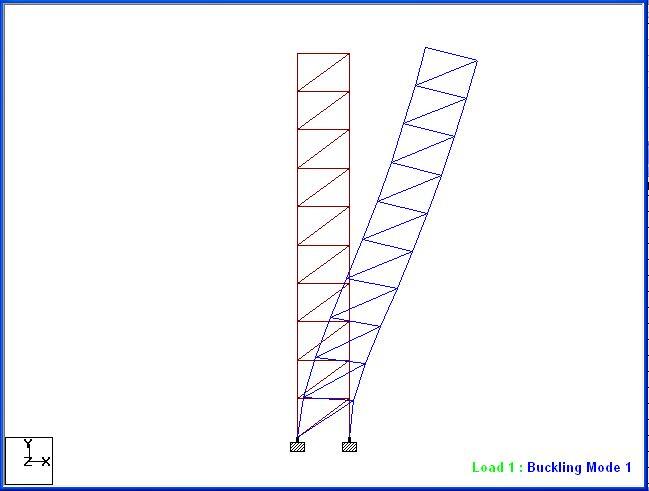
The difference obtained in the analysis result is 10.1%, but the continuum method appears to be more conservative than finite element analysis. According to Zalka (2013), the maximum error (difference obtained from finite element analysis result) expected from using this method is 17%.
References:
Zalka K.A. (2013): Structural Analysis of Regular Multi-storey Buildings. CRC Press Taylor and Francis Group


