Bridge pier caps are horizontal structural members used for transferring bridge deck loads to the piers, before they are transferred to the foundation. They can be made of different shapes or forms, depending on the required aesthetics of the bridge. However, pier caps (or heads) must be designed to resist the actions transferred from traffic, self weight of the bridge deck, wind actions, or accidental actions due to vehicle impact. By the nature of their configuration, the piers and the pier cap/head of bridges should be designed as monolithic rigid frames.
However, some of the different configurations that are obtainable in bridge piers are;
- Solid wall pier
- Hammer head bridge pier
- Rigid frame bridge pier
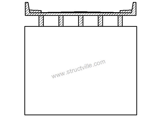
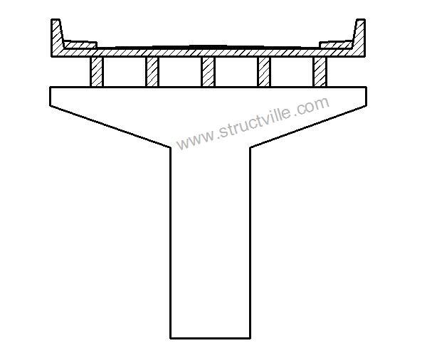
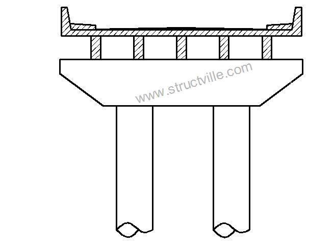
In this article, we are going to show how to design reinforced concrete rigid frame bridge pier and pier cap using Staad Pro software. Different methods can be used for obtaining the reactive forces from the bridge deck such as grillage analysis, finite element analysis, or classical methods such as Courbon’s theory. We will pick the reactive forces from finite element analysis, and apply them to the bridge pier cap.
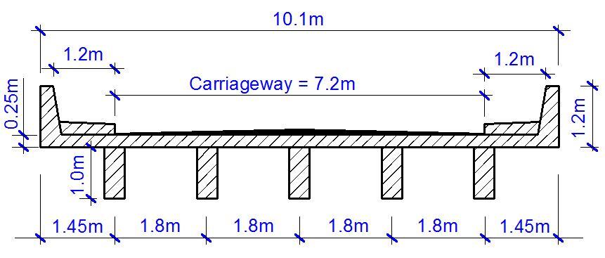
The configuration of the bridge deck is shown below;
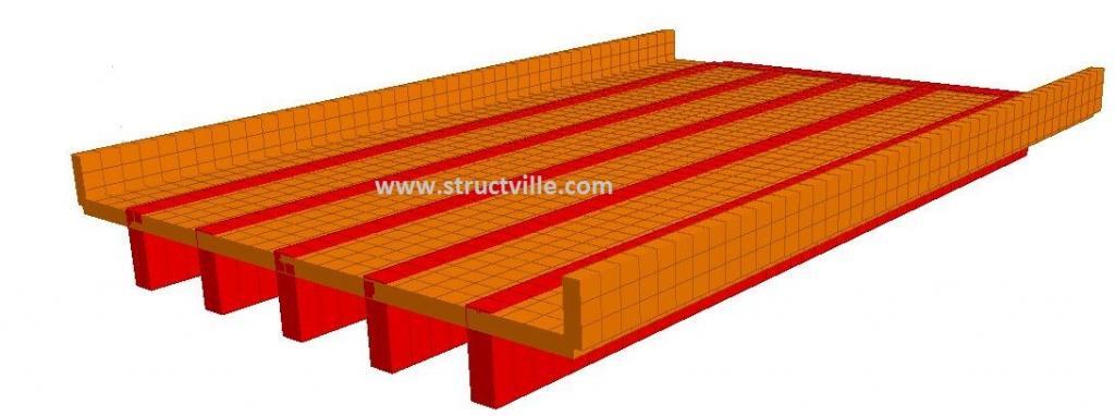
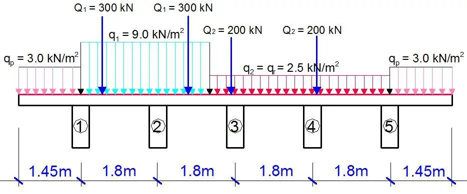
The length of the bridge deck is 15 m, and the loading and configuration is shown below;
The maximum reactive forces from finite element analysis are as follows;
Self weight = 276.288 kN
Traffic UDL = 194.839 kN
Traffic moving load = 320.762 kN
These reactions are transmitted through the elastomeric pad bearing to the pier cap. Note that there are accompanying horizontal actions due to braking, acceleration forces, skidding of vehicles etc. Design value of braking or acceleration forces depend on the vertical loads applied on notional lane 1. The values of horizontal forces should be combined with appropriate value for vertical traffic load corresponding to its frequent value. However, when the leading traffic loads are vertical ones, the accompanying value of the braking and acceleration forces are to be defined in the National Annex and can be set to zero. But for simplicity, horizontal actions have not been considered in this article.
Therefore the ultimate load that will be transferred to the pier cap is given by;
VEd = 1.35Gk + 1.5Qk = 1.35(276.288) + 1.5(194.839 + 320.762) = 1146.39 kN
Since this is assumed to be an intermediate pier, the pier cap will be subjected to double of the load above. Therefore, the maximum ULS load from each girder will be 1146.39 x 2 = 2239 kN. Note that the factored self weight of the pier and pier cap should be included in the model.
Fro proper analysis and design of the foundation, it is important to separate the service and ultimate loads properly. At SLS, the maximum reactive force from each girder is 791.889 kN. The preliminary sizing of the rigid frame pier cap and the design data of the pier system is shown below;
Diameter of piers = 1200 mm
Dimensions of pier cap = 950 x 1200 mm
Support of frame = Fixed
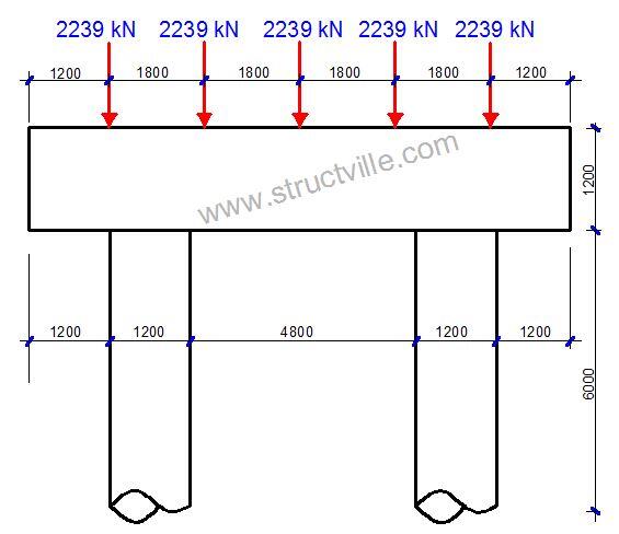
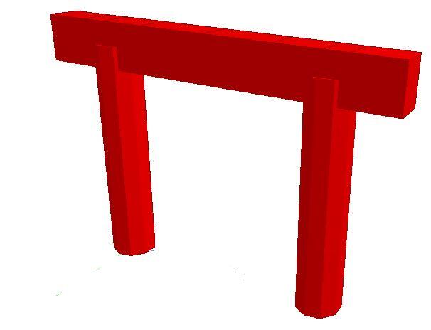
When analysed on Staad Pro, the internal forces in the rigid frame pier cap are as follows;
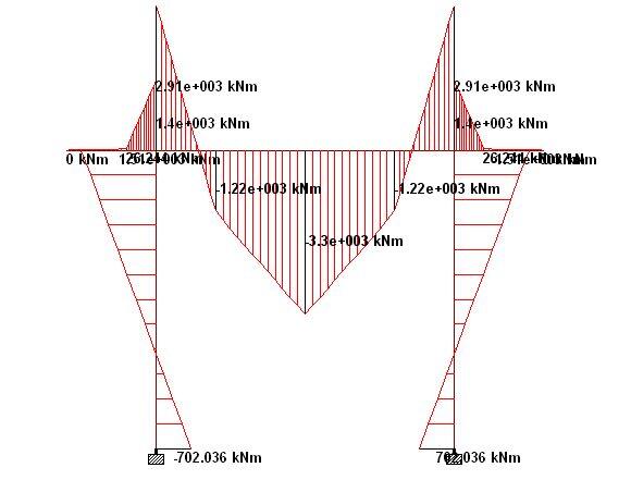
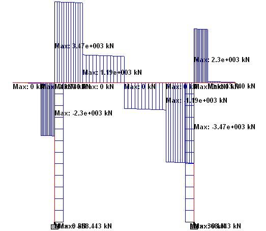
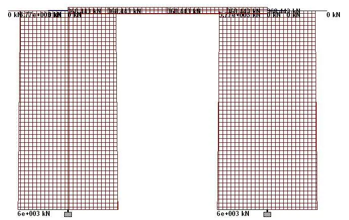
The summary of the internal forces at ULS are as follows;
Pier Cap
Sagging moment = 3298.257 kNm
Hogging moment = 2911.468 kNm
Maximum shear force = 3468.85 kN
Maximum axial force = 368 kN (compression)
Piers
Maximum moment = 1508.62 kNm
Maximum shear force = 368.443 kN
Maximum axial force = 6001.483 kN
Structural design of the Pier Cap
Let cover to reinforcements = 50 mm
Yield strength of reinforcement fyk = 500 MPa
Compressive strength of concrete fck = 40 MPa
Span – Sagging
MEd = 3298.257 KN.m
Effective depth (d) = h – Cnom – ϕ/2 – ϕlinks
Assuming ϕ25 mm bars will be employed for the main bars, and ϕ12 mm bars for the stirrups (links)
d = 1200 – 50 – 12 – 12 = 1126 mm
k = MEd/(fckbd2) = (3298.257 × 106)/(40× 950 × 11262) = 0.0684
Since k < 0.167, no compression reinforcement required
z = d[0.5+ √(0.25 – 0.882k) ]
z = d[0.5+ √(0.25 – 0.882(0.0684))] = 0.935d
As1 = MEd/(0.87yk z) = (3298.257 × 106)/(0.87 × 500 × 0.934 × 1126) = 7209 mm2
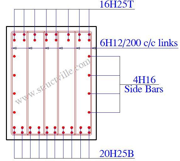
Provide 20H25mm BOT (ASprov = 8380 mm2)
Hogging
MEd = 2911.468 KN.m
k = MEd/(fckbd2) = (2911.468 × 106)/(40 × 950 × 11262) = 0.0604
Since k < 0.167, no compression reinforcement required
z = d[0.5+ √(0.25 – 0.882K)]
z = d[0.5+ √(0.25 – 0.882(0.0604))] = 0.943d
As1 = MEd/(0.87fyk z) = (2911.468 × 106)/(0.87 × 500 × 0.943 × 1126) = 6303 mm2
Provide 16H25mm TOP (ASprov = 6704 mm2)
Shear Design (Support A)
VEd = 3468.85 kN
NEd = 368 KN (compression)
We are going to anchor the 16No of H25mm reinforcement provided fully into the supports.
VRd,c = [CRd,c.k.(100ρ1 fck)(1/3) + k1.σcp]bw.d
Where;
CRd,c = 0.18/γc = 0.18/1.5 = 0.12
σcp = NEd / bd = (368 × 1000) / (950 × 1126) = 0.344 N/mm2
k = 1 + √(200/d) = 1 + √(200/1126) = 1.42> 2.0, therefore, k = 1.42
ρ1 = As/bd = 6704/(950 × 1126) = 0.00627 < 0.02; K1 = 0.15
VRd,c = [0.12 × 1.42(100 × 0.00627 × 40 )(1/3) + (0.15 × 0.344)] × 950 × 1126 = 588745.259 N = 588.745 KN
Since VRd,c (588.745 KN) < VEd (3468.85 KN), shear reinforcement is required.
The compression capacity of the compression strut (VRd,max) assuming θ = 21.8° (cot θ = 2.5)
VRd,max = (bw.z.v1.fcd)/(cotθ + tanθ)
V1 = 0.6(1 – fck/250) = 0.6(1 – 40/250) = 0.504
fcd = (αcc ) fck)/γc = (1 × 40)/1.5 = 26.667 N/mm2
Let z = 0.9d
VRd,max = [(950 × 0.9 × 1126 × 0.504 × 26.667) / (2.5 + 0.4)] × 10-3 = 4461.811 kN
Since VRd,c < VEd < VRd,max
Hence, Asw/S = VEd/(0.87fykzcot θ) = 3468850/(0.87 × 500 × 0.9 × 1126 × 2.5) = 3.147
Minimum shear reinforcement;
Asw/S = ρw,min × bw × sinα (α = 90° for vertical links)
ρw,min = (0.08 × √(fck))/fyk = (0.08 × √40)/500 = 0.001012
Asw/S (min) = 0.001012 × 950 × 1 = 0.961
Maximum spacing of shear links = 0.75d = 0.75 × 1126 = 844.5 mm
Provide 6H12mm @ 200mm c/c (Asw/S = 3.39) Ok
Note that this link must be properly closed with adequate anchorage length, because it will assist in resisting torsion.
Side Bars
Provide H16@200 c/c
The typical detailing of the pier cap is shown below. Note that bar marks and layer information were not included.
Design of the piers
You are expected to go through the process of designing columns according to Eurocode 2. You will need to check if the column is short or slender. If the column is slender, you will need to obtain the additional moments due to second order effects.
However for simplicity in this post, let us add the effect of imperfection to the column moment. You can go through the rigourous process of ensuring that you are designing for the worst effect.
Let us assume that effective length of the pier is 0.85L = (0.85 x 6000) = 5100 mm (note that Eurocode requires a more rigourous approach for calculating the effective length of columns)
The geometric imperfection of the column ei = [(1/200) x (5100/2)] = 12.75 mm
eiNEd = 6001.483 x 0.01275 = 76.5189 kNm
Let us therefore take the column design moment MEd to be = 1508.62 + 76.5189 = 1585.13 kNm
Hence,
NEd = 6001.483 kN
MEd = 1585.13 kNm
d = 1200 – 50 – 50 = 1100
d/h = 0.9 (say)
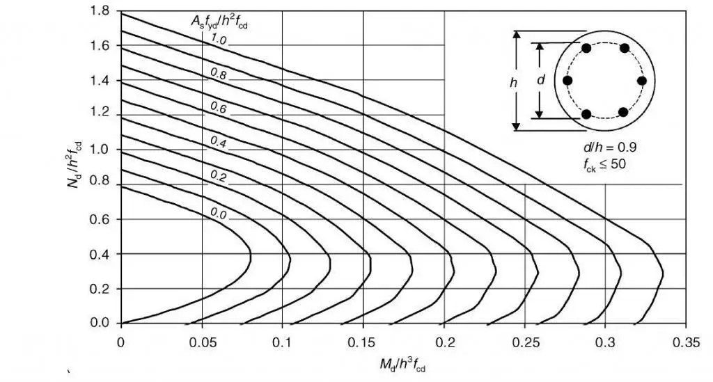
Let fcd = (0.85 x 40)/1.5 = 22.667 N/mm2
NEd/h2fcd = (6001.483 x 1000)/(12002 x 22.667) = 0.183 (Conservatively say 0.2)
MEd/h3fcd = (1585.13 x 106)/(12003 x 22.667) = 0.04
Therefore, Asfyd/h2fcd = 0.1
As.req = (0.1 x 12002 x 22.667)/(0.87 x 500) = 7504 mm2
The minimum area steel required is 0.1NEd/fyd = 1379 mm2 or 0.002Ac = 2262 mm2 whichever is greater.
Therefore provide 20H25 (Asprov = 8380 mm2)
To determine the shear reinforcement, shear design should be carried out. The reinforcement provided should be used to check the pier against vehicle collision. Note that this accidental load case should be unfactored and considered to be acting alone.




Hello and thanks for your effort, would you mind sharing the analysis and design of the rectangular girder in the example above?
Dear Eng. O. Ubani
I would like to thank you very much for all information, and analysis related to Bridges Engineering …
Kind Regards,
Ali
E-mail: dr.samirali@hotmail.com
Dear Eng. O. Ubani
I would like to thank you very much for all information, and analysis related to Bridges Engineering …
Kind Regards,
Ali
Sir, Ubani Obinna, the analysis is very much detail and impressive. Have learned many things. Thanks for your great effort. God bless
I am glad that you find our publications helpful
Thank you sir. Where do I get the design chart you used to find the area of steel required . Thanks
Sir Can You Pleas give the PDF of the given Calculations?
Very detailed design and analysis with shop drawings presentation .
Thanks for the great explanation .
Subject: Inquiry on PC T-Type Girder Bridge Design Analysis and Loading
Dear Engineer
I hope this email finds you well. I would like to express my gratitude for your meticulous work on the bridge design. I am interested in learning more about the process of analyzing loading on bridges, specifically the PC T-type girder bridge design (superstructure).
Could you please provide a file or relevant information that details the considered loads, factors, and the method by which they are analyzed and combined to determine reactions into supports? I am trying to analyze this but am having difficulty understanding the exact loads involved and the analysis, as it seems to be under standard specifications that are unfamiliar to me. The structure I am analyzing appears to have been designed using Japanese AASTO standards. Any insights or knowledge you could share on this matter would be greatly appreciated.
Thank you very much for your time and assistance. I look forward to hearing from you soon.
Kind regards,
Precious Kamndaya
Email: precious.kamndaya@gmail.com