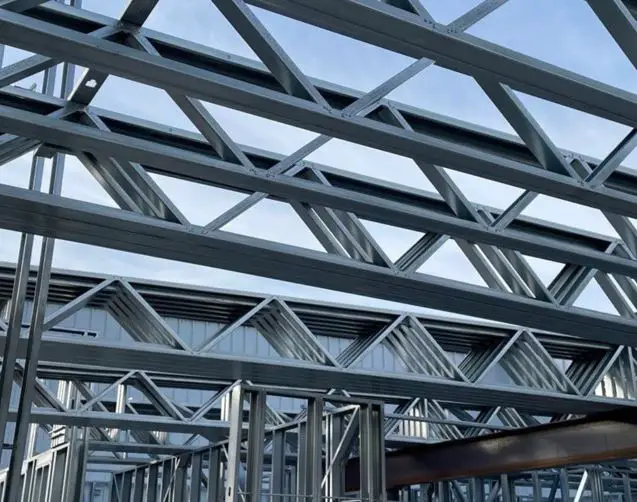
Like hot-rolled steel structural elements, light gauge steel structural elements (cold-formed steel sections) require well-designed connections for stability. Cold-formed steel sections are popularly used as secondary steelwork members in structures and as full structural framing elements. In this article, we will discuss the various methods of connecting light gauge (cold-formed) steel structures.
Cold-formed steel sections are characterised by their lightweight with thicknesses generally ranging from 1.0 mm to 3.0 mm. These sections are produced through cold-rolling or brake-pressing process and are typically manufactured into channel, Z, hat, and other open profiles. They are commonly fabricated using steel with a yield stress of 350 MPa (normal steel), with recent advancements allowing for the use of high-strength steel up to 550 MPa.
Various methodologies exist for the connection of light gauge steel sections, some of which are discussed in the subsequent section of this article. The design and detailing guidance for common connection types is provided in Section 8 of BS 5950-5. EN 1993-1-3 covers the design of cold-formed steel connections for building applications.
However, it is important to know that manufacturers, contractors, and fabricators select connection methods suited for their specific framing system, considering design parameters, detailing requirements, construction feasibility, and the availability of supporting test data.
Common Types of Light Gauge Steel Framing Connection
In cold-formed steel structures, nine common joining methods are prevalent within the construction industry. These include bolted connections, self-tapping screws, blind rivets, powder-actuated pins, spot welding, puddle welding, clinching, self-piercing rivets, and nailing. Some of these methods are discussed below:
Bolted Connection
Bolted connections are frequently used for connecting light gauge steel sections due to the efficient punching of bolt holes during the roll-forming process. Connection design typically orients the bolts to primarily resist shear loads.
The principal failure modes observed in bolted cold-formed section connections include tear-out, bearing failure of the connected material, tensile failure of the net section, shear failure of the bolts, and combined failure modes involving two or more of these mechanisms. The connection’s load-carrying capacity is usually limited by the bearing strength of the thinner connected material.

While EN 1993-1-8 differentiates between connections and joints, this distinction is not typically significant in the context of cold-formed steel (CFS) sections. For light-gauged steel sections, elastic analysis is the recommended approach for joint design.
Bolted connections are commonly employed in CFS framing to provide resistance to shear, tension, or moment forces. For a single 12mm diameter bolt, the shear resistance ranges from 8 – 12 kN.
Welded Connection
Light gauge steel structures can be welded. The shear strength capacity of the weld can be as high as the shear strength resistance of the section itself. Welded cold-formed structures can be connected using continuous MIG welding or spot welding.
MIG welding: Continuous Metal Inert Gas (MIG) welding is a viable connection technique for light gauge steel sections. However, due to the thinness of the parent metal, careful process control is required to prevent damage to the main steel section during welding. Welding galvanized steel necessitates specialized procedures. After welding, the affected areas should be treated with zinc-rich paint to enhance the steel’s durability.
Spot Welding: Resistance spot welding is typically employed in the workshop fabrication of cold-formed steel sections. This process utilizes an electric arc generated between electrodes positioned on opposing sides of the steel members to be joined.
A minimum of three spot welds is recommended for each connection to ensure adequate structural integrity. Spot welding is best suited for applications where the welding apparatus can be readily supported and manipulated for the welding process.
Screwed Connections
Self-drilling, self-tapping screws are also common methods for joining cold-formed steel sections. These screws facilitate hole formation and thread creation in a single operation, streamlining the connection process. Screwed connections are usually employed for on-site connection of wall panels or stick-built frames, however, care must be taken to prevent interference between protruding screw heads and subsequent finishes. A minimum of two screws should be utilized at each connection point.
Furthermore, these screws are also widely used for attaching finishing materials, including plasterboard, sheathing, flooring, insulation, and decking, to light steel structures. Stand-off screws, characterized by a discontinuous thread, are suitable for securing cellular insulation boards to light steel members, thereby reducing the risk of compressing the insulation.
However, screws frequently experience in-situ conditions that can negatively impact their load-carrying capacity. These conditions include construction tolerances that induce combined shear and bending stresses (rather than pure shear) within the screw, overtightening leading to thread stripping or head shearing, non-perpendicular fastener insertion, and accidental impacts on the structure resulting in dynamic loading of the fastener.
Blind Riveted Connection
Blind rivets are installed by inserting them into pre-drilled holes and then using a specialized tool to draw a mandrel, causing the rivet to expand and fill the hole. This method provides a relatively robust connection with good pull-out resistance, making it particularly suitable for joining thin materials, such as the seams of profiled decking and sheeting.

Self-piercing Riveted Connection
Self-piercing riveting eliminates the requirement for pre-formed holes in the joined components, as the rivet is designed to pierce and create a permanent fastening in a single operation. This process necessitates a hydraulically operated tool capable of accessing both sides of the joint. The formation of the riveted connection occurs in two distinct phases:
Flaring Phase: During the final stage of punch displacement within the lower sheet, the material is deformed into the die, causing the rivet shank to flare outward and mechanically interlock with the joined materials.
Piercing Phase: The rivet shank functions as a shearing punch, perforating the upper material layers and partially penetrating the lower layer until it interacts with the reacting die.
The shear capacity of riveted joints should be verified through tests.
Press joining or clinching
Clinching is a joining process that utilizes a combination of drawing and forming to mechanically interlock two or more layers of thin-gauge steel. The process employs a hydraulically actuated punch to press the metal layers into a die, creating an impression. Subsequent force application spreads the top layer of steel into the bottom layer, thereby preventing the pulling off of the top layer.
Two primary clinching methods exist:
(a) Cut Clinch: This method involves shearing the metal on two sides, drawing the top layer through slits created in the bottom layer, and then expanding the drawn portion to create a locking mechanism on both sides.
(b) Button (or Round) Clinch: This method is characterized by the formation of a “button” on one side of the joined material. The metal layers are drawn into a circular dovetail, the diameter of which is subsequently expanded to secure the sheets together.
Powder Actuated Fastenings
Powder-actuated fasteners are suitable for joining light steel members to concrete, masonry, or thick steel members. However, their application is precluded for connecting thin steel members due to the susceptibility of the connected parts to deflection under the driving force.
Conclusion
The design of light-gauge steel section connections, in accordance with Eurocode 3 Part 1-8, requires careful consideration of several factors to ensure adequate performance. The thin-walled nature of cold-formed steel sections results in distinct failure modes and significant deformations, with buckling being a primary concern in connection structural analysis.
However, the Eurocode formulations, originally developed for hot-rolled steel joints, may not accurately reflect the behavior of bolted light gauge steel connections. Therefore, further research may be required to enhance the reliability of code-based connection design for CFS sections.
Numerical modeling using finite element software offers a cost-effective and efficient alternative to extensive physical testing for investigating the behavior of bolted CFS connections. While numerical analysis allows for the examination of numerous design parameters without the substantial costs and time associated with laboratory testing, experimental validation through laboratory analysis remains crucial for corroborating numerical model data.
It is important to understand that exact site connection details are actually project-specific; however, steel-to-steel connections of light gauge sections typically employ either self-drilling, self-tapping screws or 10-12 mm diameter, Grade 4.6 bolts.
Panel-to-panel connections generally utilize a minimum of three 10 mm bolts, evenly spaced throughout the story height, or seven 4.8 mm diameter self-drilling, self-tapping screws (one at the base, one at mid-height, and five at the head). The concentration of fasteners at the panel head facilitates wind load sharing between adjacent braced panels or the transfer of tie forces necessary for structural robustness.
Ground-level panel attachment is achieved using bolts, at braced panel points, or powder-actuated fasteners along the base track. Inter-story connections between the base of the upper wall section and the head of the lower wall section can be made with either self-drilling, self-tapping screws or bolts. While self-drilling, self-tapping screws may be generally preferred, bolts are likely to be used at locations of high stress concentration, such as at the intersection of braced bays.

