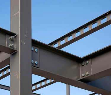
It is very common to see bending moment and shear force act simultaneously in structural members. However, when the shear force under consideration is low, the effect of shear on moment resistance of the section can be ignored. Clause 6.2.8(2) of Eurocode 3 (EN 1993-1-1:2005) states that provided the applied shear force is less than half the plastic shear resistance of the cross-section its effect on the moment resistance may be neglected. The exception to this is where shear buckling reduces the resistance of the cross-section.
When the applied shear force is greater than half the plastic shear resistance of the cross-section, the moment resistance should be calculated using a reduced design strength for the shear area using equation (1).
fyr = (1 – ρ)fy —– (1)
Where;
ρ = (2VEd/Vpl,Rd – 1)2 for (VEd > 0.5Vpl,Rd)
An alternative to the reduced design strength for the shear area, defined by equation (1), which involves somewhat tedious calculations, is equation (2). Equation (2) may be applied to the common situation of an I section (with equal flanges) subjected to bending about the major axis. In this case, the reduced design plastic resistance moment allowing for shear is given by;
My,V,Rd = [(Wpl,y – ρAw2/4tw)fy]/γm0 —– (2)
Where;
Aw = hwtw
Solved Example
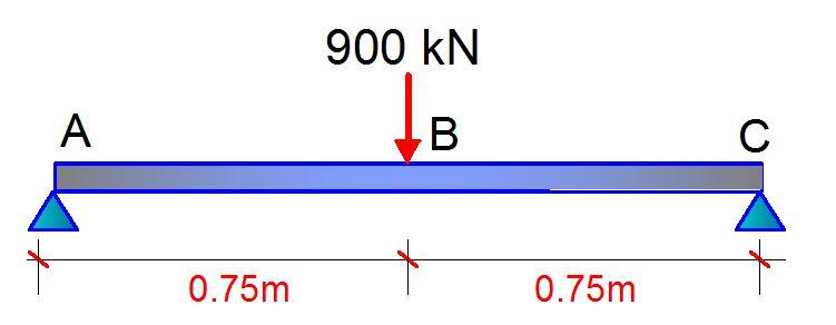
A short-span (1.5 m), simply supported, laterally restrained beam is to be designed to carry a central point load of 900 kN, as shown below. Assess the suitability of 406 x 178 x 74 UKB in grade S275 steel to carry the load.

For the beam loaded as shown above;
MEd = PL/4 = (900 x 1.5)/4 = 337.5 kNm
VEd = P/2 = 900/2 = 450 kN
Since an advanced UK beam S275 is to be used for this design;
fy = 275 N/mm2
γm0 = 1.0 [Clause 6.1(1) NA 2.15 BS EN 1993-1- 1:2005]
Try section 406 x 178 x 74 UKB
Read Also….
Design of Steel Beams to BS 5950 – 1: 2000
Structural Analysis of Compound Arch-Frame Structure
Properties
h = 412.8 mm; b = 179.5 mm; tw = 9.5 mm; tf = 16.0 mm r = 10.2mm; A = 9450 mm2; Wpl,y = 1501000 cm3
hw = h – 2tf = 380.8 mm
E (Modulus of elasticity) = 210000 N/mm2 [Clause 3.2.6(1)]
Classification of section
ε = √(235/fy) = √(235/275) = 0.92 (Table 5.2 BS EN 1993-1- 1:2005)
Outstand flange: flange under uniform compression cf = (b – tw – 2r)/2 = [179.5 – 9.5 – 2(10.2)]/2 = 74.8 mm
cf/tf = 74.8/16.0 = 4.68
The limiting value for class 1 is c/tf ≤ 9ε = 9 × 0.92
4.68 < 8.28
Therefore, outstand flange in compression is class 1
Internal Compression Part (Web under pure bending)
cw = d = h – 2tf – 2r = 412.8 – 2(16) – 2(10.2) = 360.4 mm
cw/tw = 360.4/9.5 = 37.94
The limiting value for class 1 is c/tw ≤ 72ε = 72 × 0.92 = 66.24
37.94 < 66.24
Therefore, the web is plastic. Therefore, the entire section is class 1 plastic.
Bending Moment Resistance
MEd/Mc,Rd ≤ 1.0 (clause 6.2.5(1))
Mc,Rd = Mpl,Rd = (Mpl,y × Fy)/γm0
Mc,Rd = Mpl,Rd = [(1501 × 103 × 275)/1.0] × 10-6 = 412 kNm
MEd/Mc,Rd = 337.5/412 = 0.819 < 1.0 Ok
Shear Resistance (clause 6.6.2)
The basic design requirement is;
VEd/Vc,Rd ≤ 1.0
Vc,Rd = Vpl,Rd = Av(Fy / √3)/γm0 (for class 1 sections)
For rolled I-section with shear parallel to the web, the shear area is;
Av = A – 2btf + (tw + 2r)tf (for class 1 sections) but not less than ηhwtw
Av = 9450 – (2 × 179.5 × 16) + [9.5 + 2(10.2)] × 16 = 4184 mm2
η = 1.0 (clause NA.2.4 of the UK National Annex)
ηhwtw = (1.0 × 380.8 × 9.5) = 3618 mm2
4184 > 3618
Therefore, Av = 4184 mm2
The shear resistance is therefore;
Vc,Rd = Vpl,Rd = [4184 × (275/ √3)/1.0] × 10-3 = 664.3 kN
VEd/Vpl,Rd = 450/664.3 = 0.677 < 1.0 Ok
Since VEd (450 kN) > 0.5Vpl,Rd (332.15 kN), the reduced moment resistance due to shear needs to be calculated.
Shear Buckling
Shear buckling of the unstiffnened web will not need to be considered if;
hw/tw ≤ 72ε/η
hw/tw = 380.8/9.5 = 40.1
72ε/η = (72 × 0.92)/1.0 = 66.6
40.1 < 66 Therefore shear buckling need not be considered.
Resistance of cross-section to combined bending and shear
The applied shear force is greater than half the plastic shear resistance of the cross-section, therefore a reduced moment resistance My,V,Rd must be calculated. For an I section (with equal flanges) and bending about the major axis, clause 6.2.8(5) and equation (6.30) may be utilised.
My,V,Rd = [(Wpl,y – ρAw2/4tw)fy]/γm0 but My,V,Rd ≤ Mc,Rd
ρ = (2VEd/Vpl,Rd – 1)2 = {[(2 x 450)/664.3] – 1}2 = 0.126
Aw = hwtw = 380.8 x 9.5 = 3617.6 mm2
My,V,Rd = [(1501000 – 0.126 x 3617.62 /4 x 9.5) x 275]/1.0 x 10-6 = 400.84 kNm
400.84 kNm > 337.5 kNm Therefore section is adequate to resist combined bending and shear force on it.


Hello, kindly note that images are not loading anytime i am on this website. Any help would be appreciated?