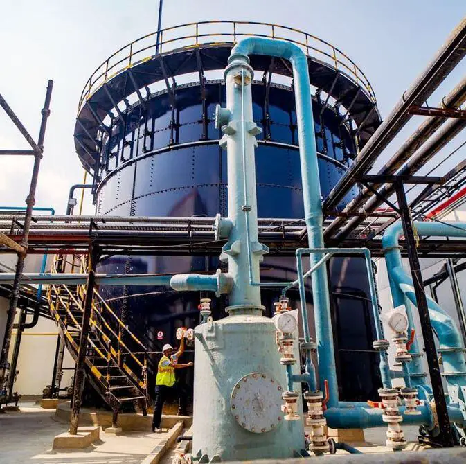
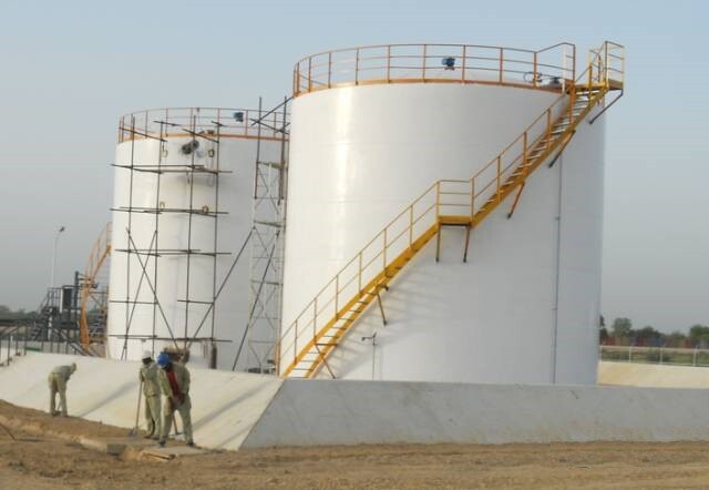
Cylindrical steel tanks are important structures used for the storage of different kinds of fluids. They are more popular in the petrochemical industry where it used for storing petroleum products, water, chemicals etc. Storage tanks are containers, either above or below the ground, that are used to store chemicals, petroleum, and other liquid products. This article is focused on the design of above above-ground cylindrical steel storage tank.
Cylindrical steel tank farms are usually constructed using a series of steel plates which are welded together on site. The thickness of the plates usually varies, usually being maximum at the bottom and minimum at the top. When the diameter of the tank is very large, internal steel columns are introduced to support the roof rafters and shell cover.
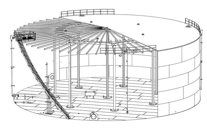
A cylindrical tank or shell may be described as thin or thick depending upon the thickness of the plate in relation to the internal diameter of the cylinder. Above-ground cylindrical tanks are typically thin-walled structures that are prone to buckling, or losing their stability, especially when they are empty or have a low liquid level. This is because external loads, such as wind and earthquakes, can more easily cause these tanks to collapse.
Traditionally, the ratio of t/d = 0.05 has been considered a suitable line of demarcation between thick and thin cylinders. If the thickness of the shell is equal to or greater than the internal diameter/20, the shell is regarded as a thick shell. In thin cylinders, the stress is usually assumed to be uniformly distributed over the wall thickness. When these storage cylinders are subjected to internal static pressure due to the stored fluid, the following types of stresses are developed.
(1) Hoop or circumferential stresses. These stresses act in a tangential direction to the circumference of the cylinder.
(2) Longitudinal stresses. These act parallel to the longitudinal axis of the shell
(3) Radial stresses. They act radially to the circumference of the shell.
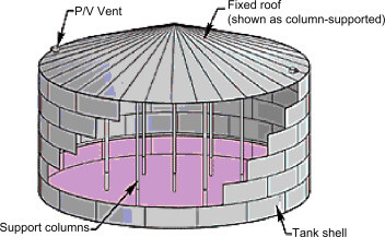
The design of cylindrical steel tanks such as tank farms usually involves the determination of the proper thickness of the tank shell that will resist the bursting force from the stored fluid, and also remain stable under the action of other external forces.
If the bursting force (pressure) = Resisting strength
Therefore,
pdl = 2ltσc
σc = pd/2t
Where;
d = internal diameter of the cylinder
t = thickness of the cylinder
p = internal pressure in the cylinder
σc = circumferential or hoop stress in the cylinder
Similarly for longitudinal stress for tanks with both ends covered with two end plates;
σl = pd/4t
Where σl = longitudinal stress
The maximum shear stress in a cylindrical shell is given by;
τmax = (σc – σl)/2 = pd/8t
Therefore, if it is required to determine the wall thickness of a thin cylindrical shell so that it can withstand a given internal pressure p, we have to determine that the maximum stress developed in the shell does not exceed the permissible tensile stress of the shell material (fy). Therefore,
t ≥ pd/2fy
Design of Cylindrical Steel Tanks
The document EN 14015:2005 provides the specifications for the structural design and verification of flat-bottomed, above-ground, welded steel tanks for the storage of liquid at ambient temperature. The EN14015 design standard uses a simplified approach to determine the thickness of tank shell courses.
This approach is based on the tank’s geometry, the liquid level, the material used, the liquid’s density, and a corrosion allowance. It aims to limit the tensile stresses in the shell due to hydrostatic pressure. However, it does not explicitly consider tank shell buckling.
Fluid Action
When a tank is in operation, the pressure load from the liquid inside it must be considered, from the maximum liquid level to when the tank is empty. The internal pressure load must also be considered, including the load due to the specified test pressure and test internal negative pressure.
For a full tank, the design hydrostatic pressure is the highest liquid pressure that acts at the bottom of the tank shell course. This is calculated as the product of the liquid’s specific weight and the maximum height of the liquid, measured from the top of the tank shell. This fluid pressure is resisted by making the bottom shell courses thicker.
In other words, the design hydrostatic pressure is the maximum pressure that the tank shell course must be able to withstand when the tank is full. This pressure is calculated based on the weight of the liquid and the height of the liquid column. The bottom shell courses are made thicker to resist this pressure.
The computation of the thickness of the tank shells is influenced by factors like the geometry of the tank, material to be contained, material strength, corrosion allowance, design pressure and height of shell courses from the top of the tank shell. Furthermore, the design of the shell for external wind loads and internal negative pressure, which is the buckling resistance of the tank shell, is prevented by providing ring stiffeners and determining the minimum spacing of secondary rings using an equivalent minimum shell thickness.
According to EN 14015:2004, the maximum allowable design stress in shell plates shall be two-thirds of the yield strength of the material with a maximum design stress of 260 MPa (when the temperature is equal to less than 100 degrees celsius). The specified thickness of the shell plates shall not be less than the specified nominal thicknesses specified in Table 16 of the code.
| Tank Diameter D (m) | Minimum nominal shell thickness (mm) for carbon and carbon manganese steels |
| D < 4 | 5 |
| 4 ≤ D < 10 | 5 |
| 10 ≤ D < 15 | 5 |
| 15 ≤ D < 30 | 6 |
| 30 ≤ D < 45 | 8 |
| 45 ≤ D < 60 | 8 |
| 60 ≤ D < 90 | 10 |
| 90 ≤ D | 12 |
The code specifies that in no case should the specified thickness of the shell or the reinforcing plate be greater than 40mm (clause 9.1.6). Also the minimum circumferential dimensions of a shell plate shall be 1m.
The required minimum design thickness of the shell plates is derived from equation (1) below or the secified values provided in Table 1, whichever is the greatest.
ec = D/20S[98W(Hc – 0.3) + p] + c —— (1)
where:
c is corrosion allowance, for the shell assumed fully painted (c = 0),
D is tank diameter in [m],
Hc is the distance from the bottom of the considered course to the design liquid height [m],
W is the maximum design density of the contained liquid under storage conditions, in kg/l
p is the design pressure [mbar],
S is the allowable design strength [MPa].
According to EN14015, 9.1.1a, the allowable design stress, S is a minimum of 2/3 of the yield strength of the shell material or 260 MPa, P is the design pressure [MPa], and W is the density of the liquid to be contained.
Hp1 = K(emin5/D3)0.5 —— (2)
where:
Hp is the minimum spacing between the stiffeners,
emin is the minimum shell thickness, and
K is a factor determined by an empirical formula in equation (3).
K = 95000/(3.563VW2 + 580PV) —— (3)
where:
VW is a 3-second gust wind speed and
PV is the design internal negative pressure.
For the specified nominal thickness of the bottom plates shall not be less than 6mm for lap welded bottoms or 5mm for butt welded bottoms (Carbon and Manganese Carbon steels) excluding the corrosion allowance. In addition, the bottom plate thicknesses in the corroded condition shall be sufficient to resist uplift due to the design internal negative pressure.
Bottom of tanks greater than 12.5m diameter shall have a ring of annular plates, having a minimum nominal thickness ea, excluding corrosion allowance either;
(a) not less than that given by the following equations;
ea = 3.0 + e1/3
where e1 is the thickness of the first course excluding corrosion allowance in mm.
But must not be greater than 6mm. Bottom of tanks up to and including 12.5m diameter may be constructed without a ring of annular plates.
Conclusion
Cylindrical steel storage tanks are one of the most common types of tanks used for storing a wide variety of liquids, including petroleum products, chemicals, and water. These tanks are typically designed to be above ground, although below-ground tanks are also used in some applications.
The design of a cylindrical steel storage tank is based on a number of factors, including the type of liquid to be stored, the tank’s capacity, and the operating conditions. The tank must be strong enough to withstand the hydrostatic pressure of the liquid, as well as any external loads, such as wind, earthquake, and snow.
The tank shell is typically made of steel plates that are welded together. The thickness of the shell plates is determined based on the design pressure and the allowable stress of the steel. The bottom of the tank is typically thicker than the sides and top to withstand the higher hydrostatic pressure at the bottom of the tank.
The tank roof can be either fixed or floating. Fixed roofs are typically used for tanks storing volatile liquids, such as gasoline, to prevent the release of vapours. Floating roofs are typically used for tanks storing non-volatile liquids, such as water, to reduce evaporation.
The construction of a cylindrical steel storage tank typically involves the following steps:
- Site preparation: The site is prepared to provide a level and stable foundation for the tank.
- Tank assembly: The tank shell is assembled by welding together the steel plates.
- Roof assembly: The tank roof is assembled and installed on the tank shell.
- Internal and external coatings: Internal and external coatings are applied to the tank to protect it from corrosion.
- Piping and instrumentation: Piping and instrumentation are installed to allow the tank to be filled and emptied, and to monitor the liquid level and pressure.
After the tank is constructed, it must be tested to ensure that it meets the design specifications. This typically involves a hydrostatic test, in which the tank is filled with water and the pressure is gradually increased to the design pressure.

