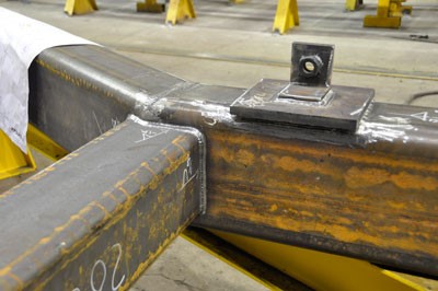
In modern construction, the commonest methods of connecting steel members are bolting and welding. Fillet welds are generally used for connecting parts where the fusion faces form an angle of between 60° and 120°. Although there are other special cases and generalities stated in the code regarding fillet weld (kindly refer).
EN 1993-1-8 (Eurocode 3 Part 8) identifies different types of welding such as;
- fillet welding
- butt welding
- plug welding,
- and flare groove welds.
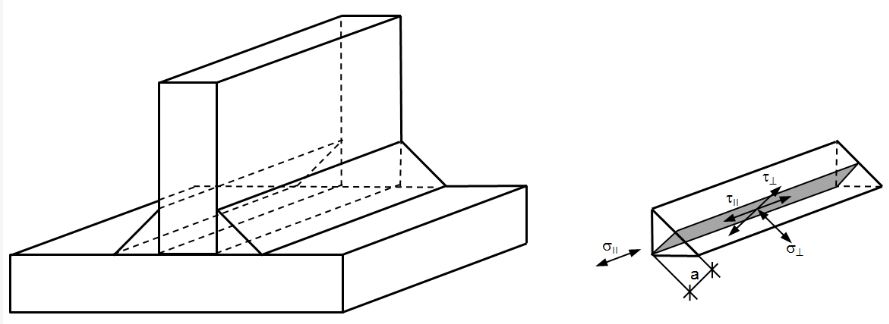
The effective weld thickness, denoted as ‘a‘, is determined by measuring the height of the largest inscribed triangle inside the fusion faces and the weld surface. This measurement is taken perpendicular to the outer side of the triangle, regardless of whether the triangle has equal or unequal legs.

Types of Fillet Welds
There are three main types of fillet welds:
- Equal leg fillet welds: These welds have legs of equal length.
- Unequal leg fillet welds: These welds have legs of different lengths.
- Lap fillet welds: These welds are used to join two pieces of metal that are overlapping.

Fillet Weld Design
The design of a fillet weld depends on the thickness of the metal being welded, the strength of the weld required, and the type of weld being used. The following factors should be considered when designing a fillet weld:
- Weld size: The weld size is the length of the weld leg. The weld size should be large enough to provide the required strength but not so large that it causes distortion of the metal.
- Weld throat: The weld throat is the thickness of the weld. The weld throat is typically equal to 0.7 times the weld size.
- Weld length: The weld length is the length of the weld along the joint. The weld length should be long enough to provide the required strength but not so long that it is wasteful of material.
According to clause 4.5.3.1(1) of EN 1993-1-8, the design resistance of a fillet weld should be determined using either the directional method or the simplified method.
Directional Method
The directional method is based on the comparison between the design tensile strength and the applied stress in the most severely loaded part of the weld throat. When using the directional method for analyzing fillet welds, the force acting on the weld is divided into components that run parallel and perpendicular to the weld throat plane. This results in evenly distributed normal and shear stresses.
The applied stress, being determined from a Von Mises formulation, accounts for the influence on the weld strength of the inclination of the resultant force per unit length to the weld axis and plane.
In the directional method, a uniform distribution of stress is assumed on the section of the weld, leading to the normal stresses and shear stresses shown in Figure 2, as follows:
σ⊥ normal stress perpendicular to weld axis
σ|| normal stress parallel to weld axis
τ⊥ shear stress (in plane of fillet weld surface) perpendicular to weld axis
τ|| shear stress (in plane of fillet weld surface) parallel to weld axis

Simplified Method
The simplified method is based on the design shear strength of the weld which is compared directly to an applied weld throat shear stress obtained by dividing the resultant force per unit of length of the weld throat size. This method does not necessitate determining the individual stress components within the weld.
Instead, the overall stress is calculated as the vector sum of all force components, and the weld’s strength is assumed to be equal to its shear strength, regardless of the force’s direction. Since fillet welds are weakest under pure shear, this method consistently produces more conservative results than the directional method.
Design Example
For the welded connection (K-Joint) in a steel truss given as shown below, establish the minimum throat thickness of the fillet weld for the gusset plate. The basic assumption is that the gusset plate transfers axial forces acting in its plane and in the direction of the member axes.
Analysis Results
NA,Ed = 250 kN (compression)
NB,Ed = 250 kN (compression)
NC,Ed = 17.5 kN (compression)
NB,Ed = 17.5 kN (compression)
Geometric Data
Gusset plate thickness tg = 10mm
Web thickness tw = 8mm
Angle between gusset and web αa = 90°
Number of fillet welds na = 1
Length of weld Lw = 400mm
Effective throat thickness a = ?
Material Data
Steel grade = S275
Yield strength fy = 275 N/mm2
Ultimate tensile strength fu = 430 N/mm2
Partial factor (resistance of weld) γM2 = 1.25 (recommended)
Design forces in the gusset plate at the chord web face
The effects of the small eccentricity from the chord axis will be neglected.
The gusset plate section is verified for the following forces:
Ng,Ed is the axial force at an eccentricity of ez = 0 to the centreline of the gusset plate
Vg,Ed is the shear force
αi = 35°
Ng,Ed = 2(250 cos 35) = 409.576 kN
Vg,Ed = 2(250 sin 35) = 286.788 kN
Assuming a uniform distribution of load in the section, the normal stress is given by;
Ag is the cross-sectional area and it is given by Ag = tg. Lw = 10mm × 400mm = 4000 mm2
σg,max = (409.576 × 1000) / (4000) = -102.394 N/mm2
The mean shear stress is given by;
τg,max = (286.788 × 1000) / (4000) = 71.697 N/mm2
By directional Method;
Assuming a uniform distribution in the throat section of the weld;
σ⊥ = the normal stress to the throat plane
τ⊥ = the shear stress (in the plane of throat) perpendicular to the axis of the weld
τ// = the shear stress (in the plane of throat) parallel to the axis of the weld
On the throat section of the weld, the force per unit length are:
Where eg is the average eccentricity. In our own case, we will be taking the eccentricity as unity.
a σ⊥ = [(102.394 × 1.0) / 1.0] / (sin 45°) = 72.403 N/mm2
a τ⊥ = [(102.394 × 1.0) / 1.0] / (cos 45°) = 72.403 N/mm2
a τ// = [(71.697 × 1.0) / 1.0] = 71.697 N/mm2
The design resistance of the fillet weld will be sufficient if the following conditions are both fulfilled:
σw = [72.4032 + 3(72.4032 + 71.6972]0.5 = 190.762 N/mm2
βw = 0.85 (Table 4.1 EN 1993-1-8:2005)
Therefore;
fu / βw.γM2 = 410 / (0.85 × 1.25) = 385.882 N/mm2
190.762 N/mm2 < 385.882 N/mm2 OK
Also verify;
0.9fu / γM2 = 0.9 × 410 / (1.25) = 295.2 N/mm2
72.403 N/mm2 < 295.2 N/mm2 OK
From these conditions, a minimum value for the effective throat thickness can be derived;
a1,min = 190.762 / 385.882 = 0.494 mm
a2,min = 72.403 / 295.2 = 0.245 mm
amin = max[a1,min , a2,min ] = 0.494 mm
However according to clause 4.5.2(2), the effective throat thickness of a fillet weld should not be less than 3mm, therefore, adopt 4mm effective throat thickness.
By Simplified Method
The design resistance of a fillet weld may be assumed to be adequate if, at every point along its length, the resultant of all the forces per unit length transmitted by the weld satisfies the following criterion (see Eurocode 3, Part 1-8):
Fw,Ed ≤ Fw,Rd
Where Fw,Ed is the design value of the weld force per unit length and Fw,Rd is the design weld resistance per unit length. The design strength resistance per unit length (Fw,Rd) is given by;
Fw,Rd = Fvw,d a
Where Fvw,d is the design shear strength of the weld and a is the throat thickness of the weld.
Fw,Ed = τg,max = (286.788 × 1000) / (400) = 716.97 N/mm (shear force per unit length of weld)
fvw,d = (430 / √3) / (0.8 × 1.25) = 233.657 N/mm2
Assuming a weld throat thickness of 4 mm
Fw,Rd = Fvw,d a = 233.657 × 4 = 934.628 N/mm
Fw,Ed (716.97 N/mm) < Fw,Rd (934.628 N/mm) Ok
Note:
According to clause 4.5.1(2) of EN 1993-1-8:2005, a fillet weld with an effective length less than 30 mm or less than 6 times its throat thickness, whichever is larger, should not be designed to carry load.
Thank you for visiting Structville today.
Our facebook page is at www.facebook.com/structville


