Beams are horizontal structural elements designed to carry lateral loads. When they are inclined or slanted, they are referred to as raker beams. Floor beams in a reinforced concrete building are normally designed to resist load from the floor slab, their own self-weight, the weight of the partitions/cladding, the weight of finishes, and other actions as may be applied. The design of a reinforced concrete (R.C.) beam involves the selection of the proper beam size and area of reinforcement to carry the applied load without failing or deflecting excessively.
Under the actions listed above, a horizontal reinforced concrete beam will majorly experience bending moment and shear force. Depending on the loading and orientation, the beam may experience torsion (twisting), as found in curved beams or beams supporting canopy roofs. For raker beams, the presence of axial force can be quite significant in the design.
Longitudinal reinforcement is used to resist bending moment, and also enhance the shear force capacity of a beam. Stirrups (links) are used for resisting any excess shear force and torsion (where applicable). In deep beams or beams subjected to torsion, sidebars can be used to enhance the torsion capacity and also prevent cracking. The depth (d), width (b), and disposition of reinforcements define the load-carrying capacity of a beam and forms the essence of their design.
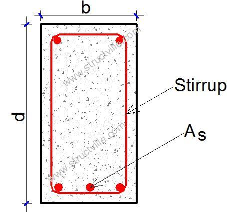
In typical reinforced concrete buildings, floor beams can be categorised into;
- T – beams,
- L – beams, or
- rectangular beams

T-beams and L-beams are generally referred to as flanged beams. T- beams are usually internal beams, while external beams (perimeter beams) are usually L – beams. Beams that are not carrying any slab load are more often rectangular beams. Beams in a reinforced concrete building can also be described in terms of their support condition such as simply supported, cantilever beams, or continuous beams.
The steps in the design of a reinforced concrete beam are as follows;
(a) Preliminary sizing of members
(b) Estimation of design load and actions
(c) Structural analysis of the beam
(d) Selection of concrete cover
(e) Flexural design (bending moment resistance)
(f) Curtailment and anchorage
(g) Shear design
(h) Check for deflection
(i) Check for cracking
(j) Provide detailing sketches
Preliminary sizing of beams
Preliminary sizing of a beam can be influenced in a lot of ways. However, deflection criteria can be used as a starting point in the analysis, even though experience is the best. Long span beams will require deeper sections, and at the same time, the magnitude of loading will also have an effect on the sizing.
Sometimes, architectural constraints can limit your options in selecting the depth and width of reinforced concrete beams. If the headroom of the building is low, you cannot afford very deep sections unless the beams are directly aligned with the partitions. The width of the block walls can also constraint the width of the beam. This is however different if a suspended ceiling will be used to conceal the beams and give the soffit of the floor a uniform look.
A general guide to the size of a beam may be obtained from the basic span-to-effective depth ratio from Table 7.4N of the BS EN 1992-1-1. The following values are can be used as a guide;
Overall depth of beam ≈ span/15.
Width of beam ≈ (0.4 to 0.6) × depth.
The width may have to be very much greater in some cases, especially when a larger width is needed to reduce the shear stress in the beam. As said earlier, the size is generally chosen from experience. Many design guides are available which assist in design.
Efective flange width of beams
Clause 5.3.2.1 of EN 1992-1-1:2004 covers the effective flange width of beams for all limit states. For T-beams, the effective flange width, over which uniform conditions of stress can be assumed, depends on the web and flange dimensions, the type of loading, the span, the support conditions, and the transverse reinforcement. The effective width of the flange should be based on the distance lo between points of zero moment, which is shown in Figure 3.
The flange width for T-beams and L-beams can be derived as shown below. The notations are shown in figure 4.
beff =Σbeff,i + bw ≤ b
where;
beff,i = 0.2bi + 0.1lo ≤ 0.2lo
and
beff,i ≤ bi
Estimation of design loads
In the manual analysis of floor beams, loads are transferred from slab to beams based on the yield line assumption. However, finite element analysis will use a numerical approach to transfer loads from the slab to the beam. The magnitude of load transferred depends on if the slab is spanning in one-way or two-way. Typically, for a two-way slab, the loads are either triangular (for the beam parallel to the short span direction of the slab) or trapezoidal (for the beam parallel to the long span direction of the slab) as shown in Figure 5.
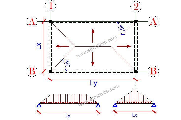
Typical load distribution from slab to beam is shown in the figure above. The analysis of trapezoidal and triangular loads on beams can be tedious especially for continuous beams with variable loading and unequal spans.
However, for beams of equal span and uniform loading, coefficients for bending moment and shear can be obtained from Chapter 12 of Reynolds and Steedman (2005). For the sake of convenience, the load transferred from the slab to the beam can be approximated as a uniformly distributed load, and the formulas for the transfer of such loads are given in Chapter 13 of Reynolds and Steedman (2005). They are presented in Table 1.
Table 1: Equivalent UDL load transferred from slab to beam
| Type of slab | UDL transferred to beam on the long Span (kN/m) | UDL transferred to beam on the short Span (kN/m) |
| One-way slab | nlx/2 | nlx/5 |
| Two-way slab | nlx/2(1 – 0.333k2) | nlx/3 |
Where;
n = ultimate pressure load on the slab = 1.35gk + 1.5qk
lx = length of short span
ly = length of long span
k = ly/lx
Beams in a building can also be subjected to other loads and the typical values are;
- Self-weight – Depends on the dimensions of the beam = (unit weight of concrete × width × depth)
- Demountable lightweight partitions = 1 kN/m2
- Block work with plaster = 3.5 kN/m2
Structural Analysis of Reinforced Concrete Beams
The primary purpose of structural analysis in building structures is to establish the distribution of internal forces and moments over the whole or part of a structure and to identify the critical design conditions at all sections. The geometry is commonly idealised by considering the structure to be made up of linear elements and plane two-dimensional elements.
Linear elastic analysis (with or without redistribution) or plastic can be carried depending on the one suitable for the problem. However for most buildings, linear elastic analysis is very adequate.
For the ultimate limit state only, the moments derived from elastic analysis may be redistributed (up to a maximum of 30%) provided that the resulting distribution of moments remains in equilibrium with the applied loads and subject to certain limits and design criteria (e.g. limitations of depth to neutral axis).
Different methods can be used for the elastic analysis of statically indeterminate beams such as;
- Moment distribution method
- Clapeyron’s theorem of three moments
- Force method
- Slope-deflection method
- Stiffness method
Some coefficients are also provided in the code of practice for the evaluation of the bending moment and shear force in continuous beams.
Concrete Cover
An adequate concrete cover should be provided in reinforced concrete beams for the following reasons;
■ safe transmission of bond forces
■ durability
■ fire resistance
The minimum cover to ensure adequate bond should not be less than the bar diameter, or equivalent bar diameter for bundled bars, unless the aggregate size is over 32 mm. Under normal conditions, concrete cover of 35mm to 40 mm is usually adequate for beams.
Flexural Design of Reinforced Concrete beams
The stress block of a singly reinforced beam section (Eurocode 2) is shown in Figure 6;
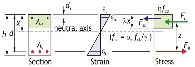
From EC2 singly reinforced concrete stress block, the moment resistance capacity of the beam MRd is given by;
MRd = Fcz —— (1)
fcd = design strength of concrete = (αccfck)/γc = (0.85 × fck)/1.5 = 0.5667fck
Compressive force in concrete = Design stress (fcd) x Area of compression block
Fc = 0.5667fck × 0.8 x b = 0.4533bfck
From the stress block distribution;
z = d – 0.4x —— (2)
Clause 5.6.3 of EC2 limits the depth of the neutral axis to 0.45d for concrete class less than or equal to C50/60. Therefore for an under reinforced section (ductile failure);
x = 0.45d —— (3)
Combining equation (1), (2) and (3), we obtain the ultimate moment of resistance (MRd)
MRd = 0.167fckbd2 ———- (4)
Also from the reinforced concrete stress block, we can obtain the tensile design moment as;
MEd = Fsz ——- (5)
Where;
Fs = fyk/1.15As1 ——-(6)
As1 = Area of tensile reinforcement required
Substituting equation (6) into (5) and making As1 the subject of the formula;
As1 = MEd/(0.87fykz) ——(7)
The lever arm z in EC2 is given from equation (2), z = d – 0.4x
Therefore, x = 2.5(d – z)
M = 0.453 × fck × b × 2.5(d – z)z
Let k = M/(fck bd2)
k can be considered as the normalised bending resistance
Hence;
M/(fck bd2) = 1.1333 [(fck bdz)/(fckbd2) – (fck bz2)/(fck bd2)]
Therefore;
0 = 1.1333[(z/d)2 – (z/d)] + k
0 = (z/d)2 – (z/d) + 0.88235k
Solving the quadratic equation;
z/d = [1 + (1 – 3.529k)0.5]/2
Rearranging;
z = d[0.5 + √(0.25 – k/1.134)] —— (8)
z = d[0.5 + √(0.25 – 0.882k)]
where ;
k = MEd/(fckbd2) —– (9)
Anchorage of Reinforced Concrete Beams
Reinforcing bars should be well anchored so that the bond forces are safely transmitted to the concrete avoiding longitudinal cracking or spalling. Transverse reinforcement shall be provided if necessary. Types of anchorage are shown in Figure 7 below (Figure 8.1 EC2).
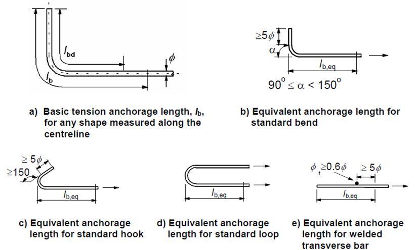
For bent bars, the basic tension anchorage length is measured along the centreline of the bar from the section in question to the end of the bar, where:
lbd = α1α2α3α4α5lb,req ≥ lb,min
where;
lb,min is the minimum anchorage length taken as follows:
In tension, the greatest of 0.3lb,rqd or 10ϕ or 100mm
In compression, the greatest of 0.6lb,rqd or 10ϕ or 100mm
lb,rqd is the basic anchorage length given by, lb,rqd = (ϕ/4)σsd/fbd
Where;
σsd = The design strength in the bar (take 0.87fyk)
fbd = The design ultimate bond stress (for ribbed bars = 2.25η1η2fctd)
fctd = Design concrete tensile strength = 0.21fck2/3 for fck ≤ 50 N/mm2
η1 is a coefficient related to the quality of the bond condition and the position of the bar during concreting
η1 = 1.0 when ‘good’ conditions are obtained and
η1 = 0.7 for all other cases and for bars in structural elements built with slip-forms, unless it can be shown that ‘good’ bond conditions exist
η2 is related to the bar diameter:
η2 = 1.0 for φ ≤ 32 mm
η2 = (132 – φ)/100 for φ > 32 mm
α1 is for the effect of the form of the bars assuming adequate cover
α2 is for the effect of concrete minimum cover
α3 is for the effect of confinement by transverse reinforcement
α4 is for the influence of one or more welded transverse bars ( φt > 0.6φ) along the design anchorage length lbd
α5 is for the effect of the pressure transverse to the plane of splitting along the design anchorage length
Curtailment of Reinforced Concrete Beams
Sufficient reinforcement should be provided at all sections to resist the envelope of the acting tensile force, including the effect of inclined cracks in webs and flanges.
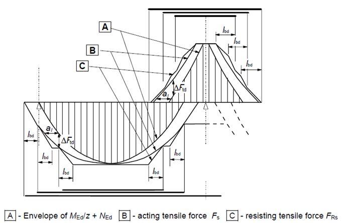
For members with shear reinforcement the additional tensile force, ΔFtd, should be calculated according to clause 6.2.3 (7). For members without shear reinforcement ΔFtd may be estimated by shifting the moment curve adistance al = d according to clause 6.2.2 (5). This “shift rule” may also be used as an alternative for members with shear reinforcement, where:
al = z (cotθ – cotα)/2 = 0.5z cotθ for vertical shear links
z = lever arm, θ = angle of compression strut
al = 1.125d when cotθ = 2.5 and 0.45d when cot θ = 1
Shear Design of Reinforced Concrete Beams

In EC2, the concrete resistance shear stress without shear reinforcement is given by;
VRd,c = [CRd,c k(100ρ1 fck )1/3 + k1.σcp]bw.d ≥ (Vmin + k1.σcp) ———- (10)
Where;
CRd,c = 0.18/γc
k = 1 + √(200/d) < 0.02 (d in mm);
ρ1 = As1/bd < 0.02 (In which As1 is the area of tensile reinforcement which extends ≥ (lbd + d) beyond the section considered)
Vmin = 0.035k(3/2)fck0.5
K1 = 0.15; σcp = NEd/Ac < 0.2fcd
(Where NEd is the axial force at the section, Ac = cross sectional area of the concrete), fcd = design compressive strength of the concrete).
The compression capacity of the compression strut (VRd,max) assuming θ = 21.8° (cot θ = 2.5)
VRd,max = (bw.z.v1.fcd )/(cotθ + tanθ) ———- (11)
v1 = 0.6(1 – fck/250)
Let z = 0.9d
If VRd,c < VEd < VRd,max
Asw/S = VEd/(0.87fykz cotθ)
If VRd,max > VEd, calculate, the compression strut angle.
θ = 0.5sin-1 [(VRd,max/bwd))/(0.153fck (1 – fck/250)] ———- (12)
If θ is greater than 45°, select another section.
Minimum shear reinforcement
Asw/S = ρw,min × bw × sinα (α = 90° for vertical links)
ρw,min = (0.08 × √fck)/fyk ———- (13)
Deflection of Reinforced Concrete Beams
A beam should not deflect excessively under service load. Excessive deflection of beams can cause damages and cracking to partitions and finishes. It can also impair the appearance of the building and cause great concern to the occupants of the building.
The selection of limits to deflection which will ensure that the structure will be able to fulfill its required function is a complex process and it is not possible for a code to specify simple limits which will meet all requirements and still be economical. Limits are suggested in the code but these are for general guidance only; it remains the responsibility of the designer to check whether these are appropriate for the particular case considered or whether some other limits should be used.
For deemed to satisfy basic span/effective depth (limiting to depth/250);
Actual L/d must be ≤ Limiting L/d × βs
The limiting basic span/ effective depth ratio is given by;
L/d = K [11 + 1.5√(fck)ρ0/ρ + 3.2√(fck) (ρ0/ρ – 1)1.5] if ρ ≤ ρ0 ——- (14)
L/d = K [11 + 1.5√(fck) ρ0/(ρ – ρ’) + 1/12 √(fck) (ρ0/ρ)0.5 ] if ρ > ρ0 —— (15)
Where;
L/d is the limiting span/depth ratio
K = Factor to take into account different structural systems
ρ0 = reference reinforcement ratio = 10-3 √(fck)
ρ = Tension reinforcement ratio to resist moment due to design load
ρ’ = Compression reinforcement ratio
The value of K depends on the structural configuration of the member and relates the basic span/depth ratio of reinforced concrete members. This is given in the table 2;
Table 2: Basic span/effective depth ratio of different structural systems
| Structural System | K | Highly stressed ρ = 1.5% | Lightly stressed ρ = 0.5% |
| Simply supported beams | 1.0 | 14 | 20 |
| End span of interior beams | 1.3 | 18 | 26 |
| Interior span of continuous beams | 1.5 | 20 | 30 |
| Cantilever beams | 0.4 | 6 | 8 |
βs = (500As,prov)/(fykAs,req) —–(16)
For flanged sections with b/bw ≥ 3, the basic ratios for rectangular sections should be multiplied by 0.8. For values of b/bw < 3, the basic ratios for rectangular sections should be multiplied by (11 – b/bw)/10. For beams with spans exceeding 7 m, which support partitions liable to be damaged by excessive deflections, the basic ratio should be multiplied by 7/span.
Check for Cracking in Reinforced Concrete Beams
According to clause 7.3.1 of EN 1992-1-1:2004, cracking is normal in reinforced concrete structures subject to bending, shear, torsion or tension resulting from either direct loading or restraint or imposed deformations. However, cracking shall be limited to an extent that will not impair the proper functioning or durability of the structure or cause its appearance to be unacceptable.
Crack width in beams may be calculated according to clause 7.3.4 of EN 1992-1-1:2004. A simplified alternative is to limit the bar size or spacing according to clause 7.3.3. If crack control is required, a minimum amount of bonded reinforcement is required to control cracking in areas where tension is expected. The amount may be estimated from equilibrium between the tensile force in section just before cracking and the tensile force in reinforcement at yielding or at a lower stress if necessary to limit the crack width.
Detailing of Reinforced Concrete Beams
The maximum and minimum areas of steel required in reinforced concrete beams are given in the Table 3.
Table 3: Reinforcement detailing of reinforced concrete beams
| Specific member issue | Value |
| Minimum area of steel required (As,min) | 0.26(fctm/fyk)btd ≥ 0.0013bd |
| Maximum areas of steel required (As,max) | 0.04bd |
| Minimum spacing of main bars | max{dg + 5mm, ϕ, 20mm} |
| Minimum area of shear links (Asw, min) | (0.08bwS√fck)/fyk |
| Maximum spacing of links | 0.75d |
In the most simplified manner, the detailing guide for beams is as shown below. However, in the most practical terms for simple residential buildings with moderate spans, reinforcements are rarely curtailed (except at the supports hogging areas) for ease in construction, especially where manual iron bending is employed. Note that to satisfy anchorage requirements, take the bob length for beams as 15 (15 x diameter of reinforcement).

Design Example of a Reinforced Concrete Beam
A continuous beam in a residential building is loaded as shown below. The beam is an L-beam with effective flange width of 895 mm. The depth and width is 450 x 230 mm. Concrete cover = 35mm, fck = 25 MPa, fyk = 460 MPa

The bending moment and shear force diagram due to the applied load is shown below;
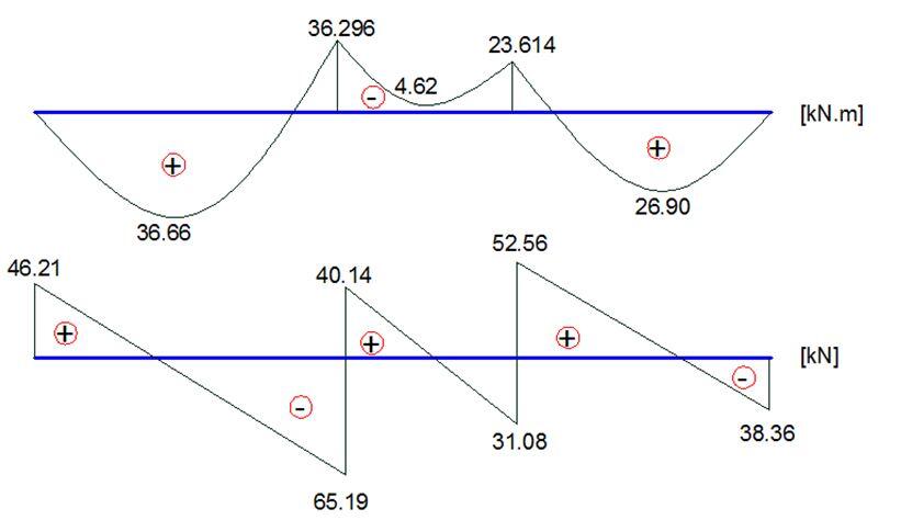
Effective depth (d) = 450 – 35 – 16/2 – 8 = 399mm
Beff = 895mm
k = MEd/(fckbeff d2) = (36.66 × 10⁶)/(25 × 895 × 3992) = 0.01029
Since k < 0.167 No compression reinforcement required
z = d[0.5 + √(0.25 – 0.882K)]
z = d[0.5 + √(0.25 – 0.882(0.01029))] = 0.95d
As1 = MEd/(0.87fyk z) = (36.66 × 10⁶)/(0.87 × 460 × 0.95 × 399) = 241.667 mm2
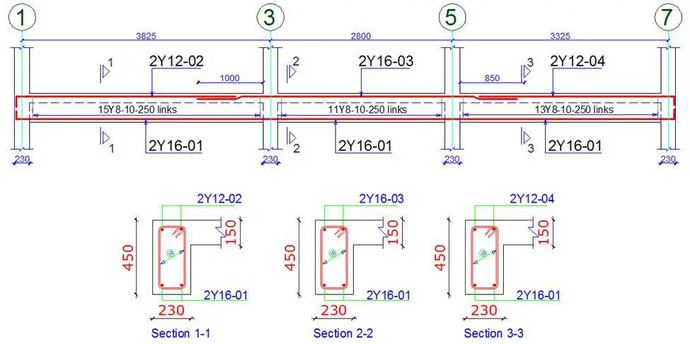
Provide 2Y16 mm BOT (As,prov = 402 mm2)
The minimum area of steel required;
fctm = 0.3 × fck2⁄3 = 0.3 × 252⁄3 = 2.5649 N/mm2 (Table 3.1 EC2)
As,min = 0.26 × fctm/fyk × b × d = 0.26 × (2.5649/460) × 230 × 399 = 133.04 mm2
Check if As,min < 0.0013 × b × d (119.301 mm2)
Since, As,min = 168.587 mm2, the provided reinforcement is adequate.
Check for deflection at the span
K = 1.3 for simply supported at one end and continuous at the other end
ρ = As/bd = 402/(895 × 399) = 0.0011257 < 10-3√25
Since ρ < ρ0
L/d = K [11 + 1.5√(fck) ρ0/ρ + 3.2√(fck) (ρ0/ρ – 1)3⁄2]
L/d = 1.3 [11 + 1.5√25 × (0.005/0.0011257) + 3.2√25 (0.005/0.0011257 – 1)3⁄2] = 1.3(11 + 33.313 + 102.158) = 190.4123
Modification factor βs = 310/σs
σs = (310fykAs,req)/(500As,prov) = (310 × 460 × 241.667)/(500 × 402) = 171.451 N/mm2
βs = 310/171.451 = 1.808
Since the beam is flanged, check the ratio of b/bw = 895/230 = 3.89
Since b/bw is greater than 3, multiply the allowable L/d by 0.8
The allowable span/depth ratio = 0.8 × βs × 190.4123 = 0.8 × 1.808 × 146.471 = 275.412
Taking the distance between supports as the effective span, L = 3825 mm
Actual deflection L/d = 3825/399 = 9.5864
Since 275.412 > 9.5864, deflection is deemed to satisfy
Use 2Y16mm for the entire bottom span.
Top reinforcements (Hogging moment)
Support 3
MEd = 36.296 KNm
Since flange is in tension, we use the beam width to calculate the value of k (this applies to all support hogging moments)
k = MEd/(fckbw d2) = (36.296 × 10⁶)/(25 × 230 × 3992) = 0.0396
Since k < 0.167 No compression reinforcement required
z = 0.95d
As1 = MEd/(0.87fyk z) = (36.296 × 10⁶)/(0.87 × 460 × 0.95 × 399) = 240 mm2
Provide 2Y16mm TOP (As,prov = 402 mm2)
Shear Design
Using the maximum shear force for all the spans
Support A; VEd = 65.19 KN
VRd,c = [CRd,c.k. (100ρ1 fck)1/3 + k1.σcp]bw.d ≥ (Vmin + k1.σcp)bw.d
CRd,c = 0.18/γc = 0.18/1.5 = 0.12
k = 1 + √(200/d) = 1 + √(200/399) = 1.708 > 2.0, therefore, k = 1.708
Vmin = 0.035k3/2fck1/2
Vmin = 0.035 × 1.7083/2 × 251/2 = 0.390 N/mm2
ρ1 = As/bd = 402/(230 × 399) = 0.00438 < 0.02;
σcp = NEd/Ac < 0.2fcd (Where NEd is the axial force at the section, Ac = cross sectional area of the concrete), fcd = design compressive strength of the concrete.) Take NEd = 0
VRd,c = [0.12 × 1.708(100 × 0.00438 × 25 )1/3] 230 × 399 = 41767.763 N = 41.767 KN
Since VRd,c (41.767) < VEd (65.19 KN), shear reinforcement is required.
The compression capacity of the compression strut (VRd,max) assuming θ = 21.8° (cot θ = 2.5)
VRd,max = (bw.z.v1.fcd)/(cotθ + tanθ)
V1 = 0.6(1 – fck/250) = 0.6(1 – 25/250) = 0.54
fcd = (αcc fck)/γc = (0.85 × 25)/1.5 = 14.167 N/mm2
Let z = 0.9d
VRd,max = [(230 × 0.9 × 399 × 0.54 × 14.167)/(2.5 + 0.4)]× 10-3 = 217.879 KN
Since VRd,c < VEd < VRd,max
Hence Asw/S = VEd/(0.87fyk zcot θ) = 65190/(0.87 × 460 × 0.9 × 399 × 2.5) = 0.18144
Minimum shear reinforcement; Asw/S = ρw,min × bw × sinα (α = 90° for vertical links)
ρw,min = (0.08 × √fck)/fyk = (0.08 × √25)/460 = 0.00086956
Asw/S (min) = 0.00086956 × 230 × 1 = 0.2000
Since 0.200 > 0.18144, adopt 0.200 as the minimum shear reinforcement
Maximum spacing of shear links = 0.75d = 0.75 × 399= 299.25
Provide Y8mm @ 250mm c/c as shear links (Asw/S = 0.4021) Ok



i really appreciate your effort of doing design hand calculations and but how i can copy and study thanks
I would like to thank you for ich great work you did, this article will help me understand more about RCC. Please share more with me
Hi UBANI
your worked examples are really helpful with clear explanation of how Eurocode is applied.
It is a helping hand to those who are stilling learning the Eurocode and switching from British Standard BS8110. Keep up the good work. Many people will benefit from your hard work.
Thank you very much Lingham
Thanks for the explanation.
Please in the detailing you are writing things like
2Y16-01 , 2Y12-02 etc. I don’t understand the meaning of 01 and 02 after the bar size please!
They are the bar marks and are used in identifying the rebars in the drawings and in the schedule.
Hello Engineer, please any idea on how we can design a long span beam with columns standing along the span ? For example, if we are building a structure where the basement is being reserved for Car packing , we need much space and then we limit the number of columns. This means the superstructure loads on some 2nd floor columns will be transmitted to the long span beams. So we have something like a transfer beam
The design concept is simple – transfer the column reactions as a concentrated load to the beams, analyse, and design accordingly.
Quite informative, simply relayed
Please if the beam is continuous L beam and Effictive flange width is not given . Can you show us how to calculate it .? And according to the spans with positive moments do we assume it T-shape?
The link below will help. Thanks
https://structville.com/2018/02/how-to-calculate-the-effective-flange-of-width-of-beams-according-to-ec2.html
If the continuous beam is L shape does that mean we will design the sagging moments ( Spans ) as L shape ? I mean when calculating beff will calculate only one side right ? thanks
Yes, beff will be calculated for one side only.
Thank you Sir
How do you design a beam with a span of 12m?
No Comment for today!
It’s an informative article to understand how to design a beam. Here are all types of beam explanations.