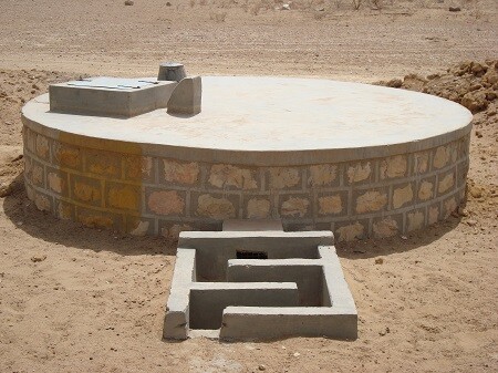
A plate is a flat structural element that has a thickness that is small compared with the lateral dimensions. Plates are bounded by two parallel planes, called faces, and a cylindrical surface called an edge or boundary. The thickness is usually constant but may be variable and is measured normal to the middle surface of the plate. Circular plates are common in many structures such as nozzle covers, end closures in pressure vessels, pump diaphragms, turbine disks, and bulkheads in submarines and airplanes, etc. They are also used as bases or covers of cylindrical water tanks and structures. When they are resting on the ground, they behave as plates on an elastic foundation.
In the elastic analysis of circular plates, it is convenient to express the governing differential equation in polar coordinates, even though rectangular (Cartesian) coordinates can be used (as applied in this article). This can be readily accomplished by a coordinate transformation and can be found in many pieces of literature.
If the coordinate transformation technique is used, the following geometrical relations between the Cartesian and polar coordinates are applicable;

x = a cosθ; y = a sinθ; x2 + y2 = a2 —- (1)
θ = tan-1(y/x)
Referring to the above;
∂r/∂x = x/r = cosθ; ∂r/∂y = y/r = sinθ
∂θ/∂x = -y/r2 = -sinθ/r; ∂θ/∂y = x/r2 = cosθ/r
The governing differential equation (biharmonic equation) for the elastic deflection of a plate in polar coordinates is given by equation (2);
∇r4w = (∂2/∂r2 + ∂/r∂r + ∂2/r2∂θ2)(∂2w/∂r2 + ∂w/r∂r + ∂2w/r2∂θ2) = q/D — (2)
This is equivalent to the moment-curvature relationship of a thin plate which is given by (3);
∂4w/∂x4 + 2∂4w/∂x2∂y2 + ∂4w/∂y4 = q/D — (3)
Where D is the flexural rigidity of the plate which is given by;
D = Eh3/12(1 – ν2) — (4)
h = thickness of the plate
E = Modulus of elasticity of the plate material
ν = Poisson ratio of the plate material
Circular Plate Clamped at the Edge and Subjected to Uniform Load
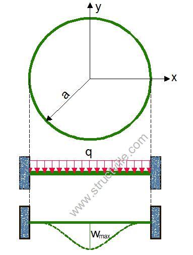
Let us consider a circular plate clamped at all edges (fixed) and subjected to a uniform lateral load q. The boundary of the plate is given by y2 + x2 = a2
For a such a clamped circular plate, the slope and deflection at the edges are zero;
w = 0; ∂w/∂x = 0; ∂w/∂y = 0 along y2 + x2 = a2
The solution to the deflection equation of the plate is given by;
w = c(x2 + y2 – a2)2 which satisfies the condition given above.
Let f(x, y) = x2 + y2 – a2
The partial derivatives are given by;
∂w/∂x = 4cxf; ∂w/∂y = 4cyf
∂2w/∂x2 = 4c(2x2 + f); ∂2w/∂x∂y = 8cxy; ∂2w/∂y2 = 4c(2y2 + f)
∂3w/∂x3 = 24cx; ∂3w/∂x2∂y = 8cy; ∂3w/∂x∂y2 = 8cx; ∂3w/∂y3 = 24cy
∂4w/∂x4 = 24c; ∂4w/∂x2∂y2 = 8c; ∂4w/∂y4 = 24c
Substituting this into the biharmonic equation, we can verify that;
c = -q/64D
Hence the elastic deflection of a circular plate clamped at all edges and subjected to a uniform lateral load is given by;
w = -q/64D(x2 + y2 – a2)2
The maximum deflection occurs at the centre of the plate and it is therefore given by;
wmax = -qa4/64D
The moments occurring in the plate from the moment-curvature equations are;
Mx = -q/16[(3 + v)x2 + (3v + 1)y2 – (1 + v)a2]
My = -q/16[(3v + 1)x2 + (3 + v)y2 – (1 + v)a2]
Mxy = q/8(1 – v)xy
The out-of-plane shear forces can be given by;
Vx = -qx/2; Vy = -qy/2
At the centre of the plate;
Mmax = q/16 × (1 + v)a2; Vx = Vy = Mxy = 0
The maximum moment occurs at the edge of the plate and it is given by Mr = -qa2/8
Simply supported circular plate subjected to a uniform lateral load
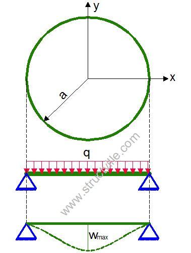
The boundary conditions are at the support, the deflection is zero, and the bending moment is zero.
w = 0; Mx = My = 0
The equation of the deflected surface is given by;
w = C3r2 + C4 + qr2/64D
The expression for the bending moment Mr can be given as;
Mr = -D[2C3(1 + v)+ qr2/16D × (3 + v)]
Introducing the equations for bending moment and deflection into the boundary conditions;
C3 = -qa2(3 + v)/32D(1 + v); C4 = qa4(5 + v)/64D(1 + v)
Therefore, the elastic deflection of a circular plate simply supported at the edges is given by;
w = [-q(a2 – r2)/64D × ((5 + v)/(1 + v) × (a2 – r2))]
The maximum deflection which occurs at x = y = 0 is therefore;
wmax = qa4/64D × (5 + v)/(1 + v)
The bending moments are as follows;
Mr = q/16(3 + v)(a2 – r2)
Mt = q/16[(3 + v)a2 – (1 + 3v)r2]
Note: r2 = x2 + y2
The maximum moment occurs at the centre of the plate (r = 0), and it is given by;
Mmax = qa2/16 × (3 + v)
Clamped circular plate with a concentrated force at the center
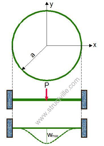
Clamped circular plate with a concentrated force P at the center, the expression for the deflection is given by;
w = P/16πD× (2r2In(r/a) + a2 – r2)
The bending moments are given by;
Mr = P/4π [(1 + v)In(a/r) – 1]
Mt = P/4π [(1 + v)In(a/r) – v]
Simply supported circular plate with a concentrated force at the center
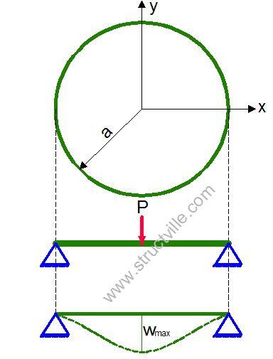
For a simply supported circular plate with a concentrated force P at the center, the expression for the deflection and bending moments are given by;
w = P/16πD× (2r2In(r/a) + (3 + v)/(1 + v) × a2 – r2)
Mr = P/4π [(1 + v)In(a/r)]
Mt = P/4π [(1 + v)In(a/r) + 1 – v]
Solved Examples on the Analysis of Circular Plates
A circular plate of thickness (150 mm) and diameter 10m is subjected to a uniform lateral load of 10 kN/m2. Calculate the deflection and bending moment at the centre of the plate assuming;
(a) Simply supported conditions
(b) Clamped edge conditions
(v = 0.2; E = 2.1 x 10⁷ kN/m2)
Solution
The flexural rigidity of the plate is given by;
D = Eh3/12(1 – ν2) = (2.1 × 107 × 0.153)/12(1 – 0.22) = 6152.34 kNm
(a) Assuming simply supported edge
(i) Maximum deflection
wmax = qa4/64D × (5 + v)/(1 + v) = (-10 × 54)/(64 × 6152.34) × (5 + 0.2)/(1 + 0.2) = 0.06877 m = 68.78 mm
(ii) Maximum bending moment
Mmax = qa2/16 × (3 + v) =(-10 × 52)/16 × (3 + 0.2) = 50 kNm
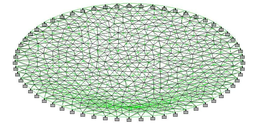
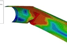
When analysed using finite element analysis on Staad Pro;
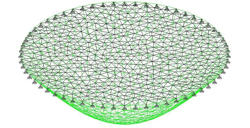
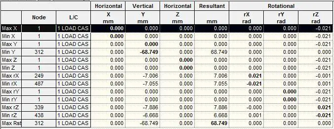
The maximum deflection at the centre of the plate was observed to be 68.749 mm as shown in the table below. This comparable with 68.78 mm obtained using classical theory.
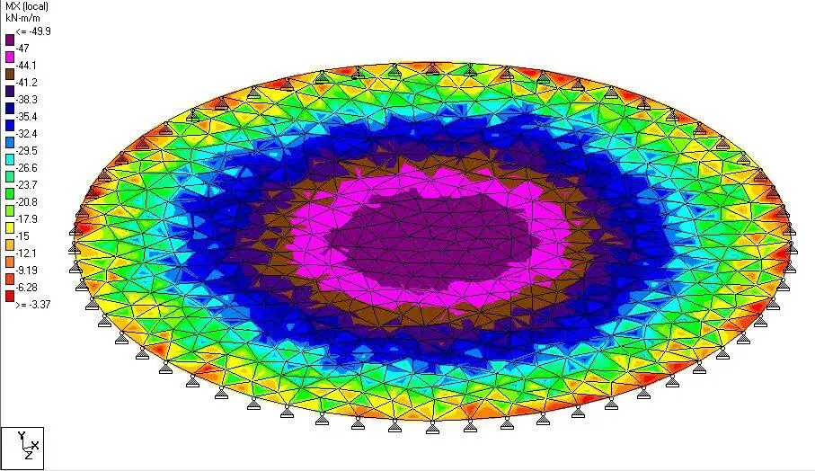
The bending moment obtained using finite element analysis was observed to be 49.9 kNm/m as shown below. A value of 50 kNm was obtained using classical theory.
(b) Assuming clamped edge conditions;
(i) Maximum deflection
wmax = -qa4/64D = (-10 × 54)/(64 × 6152.34) = 0.0158 m = 15.87 mm
(ii) Bending moment at the center
Mmax = q/16 × (1 + v)a2 = 10/16 × (1 + 0.2) × 52 = 18.75 kNm
(iii) Bending moment at the edge
Mr = -qa2/8 = (-10 x 52)/8 = -31.25 kNm
When analysed on Staad Pro;
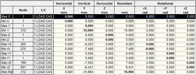
The maximum deflection at the centre of the plate was observed to be 15.964 mm (compared with the value of 15.87 mm obtained using classical theory)
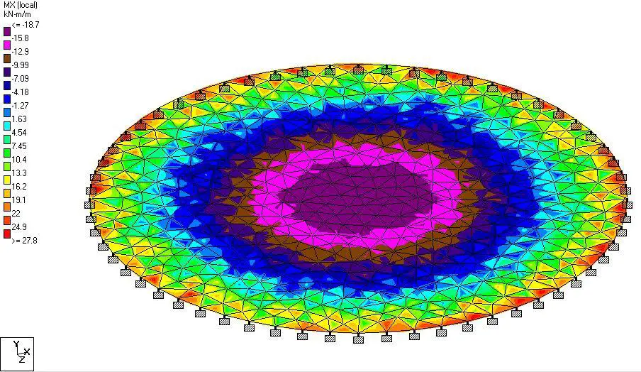
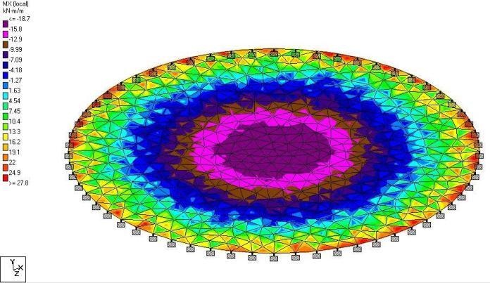
The bending moment values from the finite element analysis result are shown below;
Summary of Analysis Result
| Type of plate/Action Effect | Staad Pro (FEA) | Classical Method | Percentage Difference |
| Simply supported Deflection (mm) | 68.75 mm | 68.78 mm | -0.0436% |
| Span Moment (kNm) | 49.9 kNm | 50 kNm | -0.2% |
| Clamped Plate Deflection (mm) | 15.964 mm | 15.87 mm | 0.563% |
| Span Moment (kNm) Edge Moment (kNm) | 18.71 kNm -27.8 kNm | 18.75 kNm -31.25 kNm | -0.213% -12.41% |



What about the stresses?
In order to calculate the failure