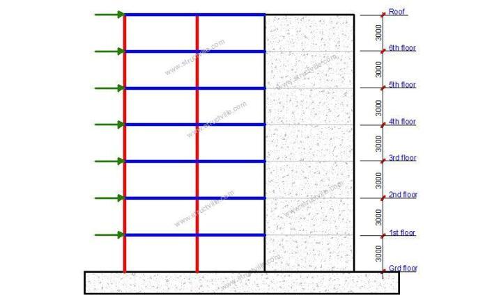
Shear walls and frames (comprising of columns and beams) are distinct structural systems that can be used in resisting lateral actions in high-rise buildings. However, as a building goes higher, frames alone become inadequate for lateral stability, hence, the structure can be augmented by shear walls and/or cores. Shear wall-frame interaction for lateral load resistance is complex because shear walls deflect primarily in bending mode, while frames deflect in shear mode.
However, the interaction between shear walls and frames is beneficial for high-rise buildings, since the linkage and stiffness of the floor slab diaphragm and the stabilising elements give better lateral load resistance. Furthermore, since their mode of deflection varies, the frame tends to restrain the shear wall in upper storeys and the shear wall tends to restrain the frame in the lower storeys. This reduces the lateral deflection and improves the overall efficiency of the structural system.
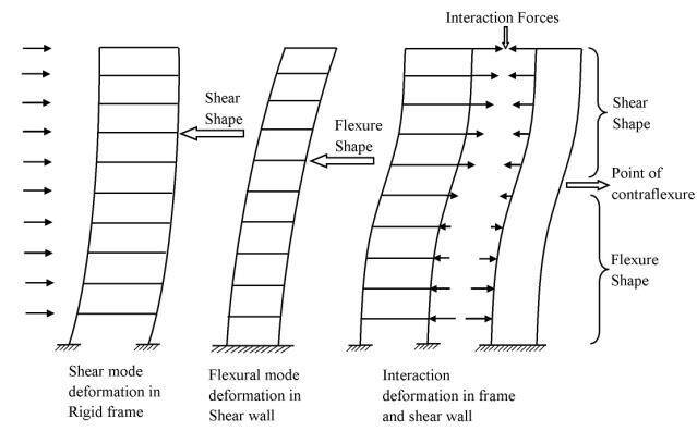
Shear walls are stiffer than columns, hence they take up most of the lateral load. This has sometimes led to the conservative approach of transferring the entire lateral load to the shear walls during design. When the building is very tall, the flexural deformation of the shear wall becomes very pronounced and hence, must be allowed for in the analysis. Shear wall-frame systems have been used successfully in buildings ranging from 10 storeys to 50 storeys.
The difference in behavior under lateral load, in combination with the in-plane rigidity of the floor slabs, causes nonuniform interacting forces to develop when walls and frames are present. This makes the analysis more difficult. If torsion is not considered in the analysis, two simplified manual methods of determining the interaction of frames and shear walls are:
- Use of charts given by Khan and Sbarounis (1964) or PCA’S Advanced Engineering Bulletin No. 14, f7), and
- Use of Equation (C) by PCA.
In order to use these charts, the structure must be reduced to a single frame and a single wall by the addition of the properties of the separate vertical units. In both references, the stiffnesses (Iw) of all the shear walls are summed to give an equivalent single wall.
In this article, we are going to investigate the effects of shear wall-frame interaction in the resistance of uniformly distributed lateral loads using finite element analysis. A 2D model of a 10-storey and 50-storey building will be used in the analysis.
Model 1A: Analysis of a 10-storey Frame Without Shear Wall
Height of building = 30 m
Inter-storey height of building = 3 m
Dimension of beams = 400 x 600 mm
Dimension of columns = 400 x 400 mm
Lateral load = 5 kN/m
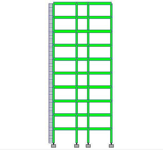
When analysed on Staad Pro software, the analysis results are as follows;
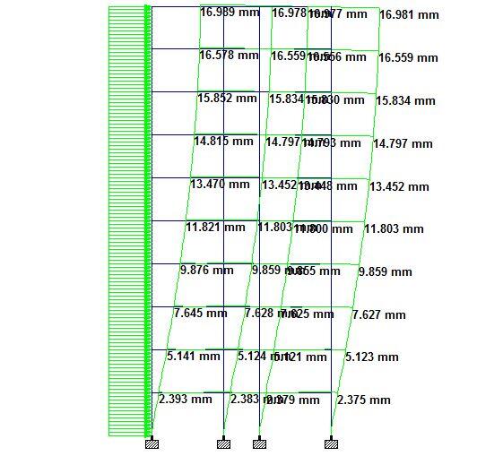
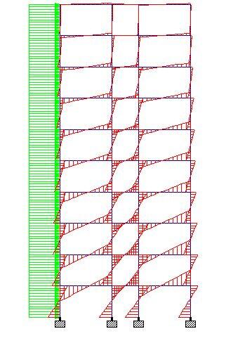
Summarily, the analysis result of the 10-storey frame without shear walls is as follows;
Deflection
Maximum deflection at roof level = 16.989 mm
Deflection at 1st floor = 2.393 mm
External Column (windward side)
Bending moment = 59.1 kNm
Shear force = 39 kN
Axial force = 146 kN
Internal Column (windward side)
Bending moment = 63.5 kNm
Shear force = 39.9 kN
Axial force = 72.8 kN
First-floor beams
Bending moment = 75 kNm
Shear force = 26.4 kN
Axial force = 7.68 kN
Model 1B: Analysis of a 10-storey frame with shear wall
Height of building = 30 m
Inter-storey height of building = 3 m
Dimension of beams = 400 x 600 mm
Dimension of columns = 400 x 400 mm
Length of shear wall = 2500 mm
Thickness of shear wall = 250 mm
Lateral load = 5 kN/m
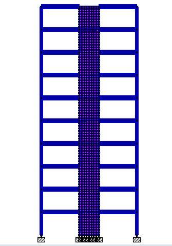
Deflection
Maximum deflection at roof level = 7.120 mm
Deflection at 1st floor = 0.319 mm
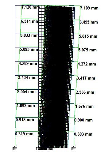
External Column (windward side)
Bending moment = 13 kNm
Shear force = 12.7 kN
Axial force = 105 kN
First-floor beams
Bending moment = 20.8 kNm
Shear force = 8.08 kN
Axial force = 18.9 kN
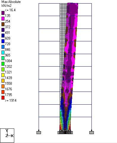
Shear Walls
Maximum absolute stress = 1913.65 kN/m2
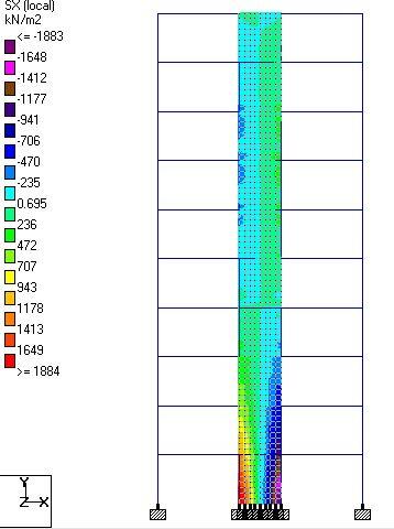
Sx = 1884.42 kN/m2
Sy = 508 kN/m2
Model 2A: Analysis of a 50-storey building without shear wall
Height of building = 150 m
Inter-storey height of building = 3 m
Dimension of beams = 400 x 600 mm
Dimension of columns = 400 x 400 mm
Lateral load = 5 kN/m
Summary of analysis results
Deflection
Maximum deflection at roof level = 1516.839 mm
Deflection at 1st floor = 13.739 mm
External Column (windward side)
Bending moment = 299 kNm
Shear force = 171 kN
Axial force = 4170 kN
Internal Column (windward side)
Bending moment = 340 kNm
Shear force = 208 kN
Axial force = 1142 kN
First-floor beams
Bending moment = 411 kNm
Shear force = 145 kN
Axial force = 7.94 kN
Read Also…
Aspects of shear wall modelling
Application of wind load to shear walls
Model 2B: Analysis of a 50-storey framed building with shear wall
Height of building = 150 m
Inter-storey height of building = 3 m
Dimension of beams = 400 x 600 mm
Dimension of columns = 400 x 400 mm
Length of shear wall = 2500 mm
Thickness of shear wall = 250 mm
Lateral load = 5 kN/m
Deflection
Maximum deflection at roof level = 1297.128 mm
Deflection at 1st floor = 2.522mm
External Column (windward side)
Bending moment = 66.5 kNm
Shear force = 38.6 kN
Axial force = 3887 kN
First-floor beams
Bending moment = 137 kNm
Shear force = 53.3 kN
Axial force = 46.5 kN
Shear Walls
Maximum absolute stress = 15734 kN/m2
Sx = 15604.6 kN/m2
Sy = 4547.11 kN/m2
Discussion of results
Model 1
| Element (Action Effect) | Without shear wall | With shear wall | Percentage Difference (%) |
| Maximum deflection | 16.989 mm | 7.120 mm | 58.09 % |
| Deflection at first storey | 2.393 mm | 0.319 mm | 86.67 % |
| Column bending moment | 59.1 kNm | 13 kNm | 78% |
| Column shear force | 39 kN | 12.7 kN | 67.43% |
| Column axial force | 146 kN | 105 kN | 28.08% |
| Beam bending moment | 75 kNm | 20.8 kNm | 72.26% |
| Beam shear force | 26.4 kN | 8.08 kN | 69.39% |
| Beam axial force | 7.78 kN | 18.9 kN | -142.93% |
Model 2
| Element (Action Effect) | Without shear wall | With shear wall | Percentage Difference (%) |
| Maximum deflection | 1516.8 mm | 1297.128 mm | 14.482 % |
| Deflection at first storey | 13.739 mm | 2.522 mm | 81.643 % |
| Column bending moment | 299 kNm | 66.5 kNm | 77.76 % |
| Column shear force | 171 kN | 38.6 kN | 77.42 % |
| Column axial force | 4170 kN | 3887 kN | 6.78 % |
| Beam bending moment | 411 kNm | 137 kNm | 66.67 % |
| Beam shear force | 145 kN | 53.3 kN | 63.24 % |
| Beam axial force | 7.94 kN | 46.5 kN | -485.642 % |
The presence of shear walls reduced the maximum lateral deflection of the 10 storey building by about 58% when compared with the 50 storey building where deflection reduced by just 14.482%. Therefore as a building gets higher, the arrangement of shear walls becomes more and more important. In a study carried out by Aginam et al (2015) at Nnamdi Azikiwe University, Awka, Nigeria, it was observed that shear wall positioning affects the lateral displacement of tall buildings. Shear walls placed externally reduced lateral deflection when compared with shear walls placed internally.
In both models, the column bending moment was reduced by about 78% when the shear wall was introduced in-between the frames. However, column axial force reduced by about 28% in the 10-storey building, while it reduced by just 6.78% in the 50-storey building. Bending moment and shear forces in beams of the framed structures reduced considerably when shear walls were introduced. On the other hand, the presence of shear walls increased the axial force in the horizontal beam members.
References
[1] Aginam C.H., Chidolue C.A., and Ubani O.U. (2015): Effect of Planar Solid shear wall-frame arrangement on the deformation behavior of multi-story frames. IOSR Journal of Mechanical and Civil Engineering 12(1):98-105
[2] Khan, F.R. and Sbarounis (1964): Interaction of Shear Walls and Frames Journal of the Structural Division, Proc.,ASCE 90(3):285-338







The infromation was very good & usefull , Thank you
Very useful article with clear explanation. Thank you !