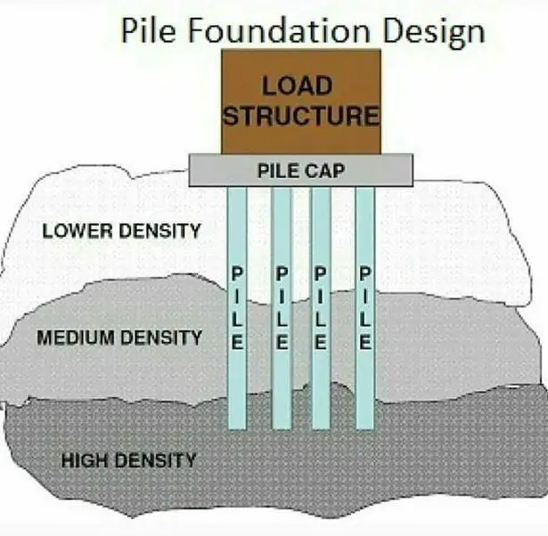
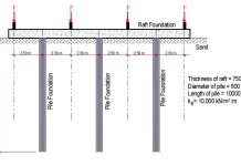
Deep foundations are employed when the soil stratum beneath the structure is not capable of supporting the load with a tolerable settlement or adequate safety against shear failure. The two common types of deep foundations are well foundations (or caissons) and pile foundations. Piles are relatively long, slender members that are driven into the ground or cast-in-situ. The design of pile foundation involves providing adequate pile type, size, depth, and number to support the superstructure load without excessive settlement and bearing capacity failure. Deep foundations are more expensive and technical than shallow foundations.
Pile Foundations can be used in the following cases;
- When the upper soil layer(s) is (are) highly compressible and too weak to support the load transmitted by the superstructure, piles are used to transmit the load to underlying bedrock or a stronger soil layer. When bedrock is not encountered at a reasonable depth below the ground surface, piles are used to transmit the structural load to the soil gradually. The resistance to the applied structural load is derived mainly from the frictional resistance developed at the soil–pile interface.
- When subjected to horizontal forces, pile foundations resist by bending while still supporting the vertical load transmitted by the superstructure. This situation is generally encountered in the design and construction of earth-retaining structures and foundations of tall structures that are subjected to strong wind and/or earthquake forces.
- In many cases, the soils at the site of a proposed structure may be expansive and collapsible. These soils may extend to a great depth below the ground surface. Expansive soils swell and shrink as the moisture content increases and decreases, and the swelling pressure of such soils can be considerable. If shallow foundations are used, the structure may suffer considerable damage.
- The foundations of some structures, such as transmission towers, offshore platforms, and basement mats below the water table, are subjected to uplifting forces. Piles are sometimes used for these foundations to resist the uplifting force.
- Bridge abutments and piers are usually constructed over pile foundations to avoid the possible loss of bearing capacity that a shallow foundation might suffer because of soil erosion at the ground surface
Classification of Piles
Piles may be classified in a number of ways based on different criteria:
(a) Function or action
(b) Composition and material
(c) Method of installation
Classification Based on Function or Action
Piles may be classified as follows based on the function or action:
End-bearing piles
Used to transfer load through the pile tip to a suitable bearing stratum, passing soft soil or water.
Friction piles
Used to transfer loads to a depth in a frictional material by means of skin friction along the surface area of the pile.
Tension or uplift piles
Uplift piles are used to anchor structures subjected to uplift due to hydrostatic pressure or to overturning moment due to horizontal forces.
Compaction piles
Compaction piles are used to compact loose granular soils in order to increase the bearing capacity. Since they are not required to carry any load, the material may not be required to be strong; in fact, sand may be used to form the pile. The pile tube, driven to compact the soil, is gradually taken out and sand is filled in its place thus forming a ‘sand pile’.
Anchor piles
These piles are used to provide anchorage against horizontal pull from sheetpiling or water.
Fender piles
They are used to protect water-front structures against impact from ships or other floating objects.
Sheet piles
Sheet piles are commonly used as bulkheads, or cut-offs to reduce seepage and uplift in hydraulic structures.
Batter piles
Used to resist horizontal and inclined forces, especially in water front structures.
Laterally-loaded piles
Used to support retaining walls, bridges, dams, and wharves and as fenders for harbour construction.
Classification Based on Material and Composition
Piles may be classified as follows based on material and composition:
Timber piles
These are made of timber of sound quality. Length may be up to about 8 m; splicing is adopted for greater lengths. Diameter may be from 30 to 40 cm. Timber piles perform well either in fully dry condition or submerged condition. Alternate wet and dry conditions can reduce the life of a timber pile; to overcome this, creosoting is adopted. Maximum design load is about 250 kN.
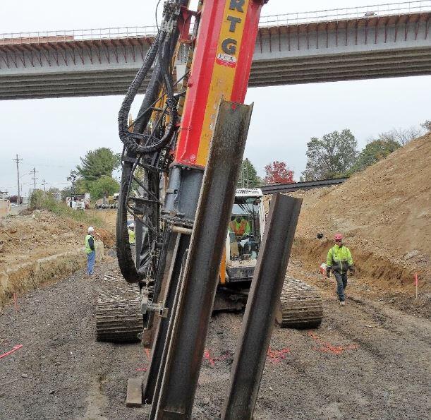
Steel piles
These are usually H-piles (rolled H-shape), pipe piles, or sheet piles (rolled sections of regular shapes). They may carry loads up to 1000 kN or more.
Concrete piles
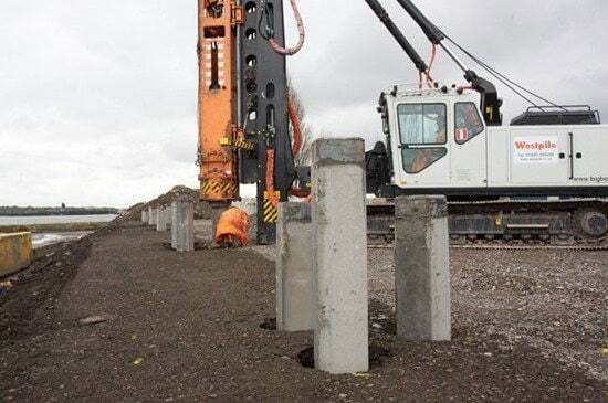
These may be ‘precast’ or ‘cast-in-situ’. Precast piles are reinforced to withstand handling stresses. They require space for casting and storage, more time to cure and heavy equipment for handling and driving. Cast-in-situ piles are installed by pre-excavation, thus eliminating vibration due to driving and handling.
Composite piles
These may be made of either concrete and timber or concrete and steel. These are considered suitable when the upper part of the pile is to project above the water table. The lower portion may be of untreated timber and the upper portion of concrete. Otherwise, the lower portion may be of steel and the upper one of concrete.
Classification Based on Method of Installation
Piles may also be classified as follows based on the method of installation:
Driven piles
Timber, steel, or precast concrete piles may be driven into position either vertically or at an inclination. If inclined they are termed ‘batter’ or ‘raking’ piles. Pile hammers and pile-driving equipment are used for driving piles.
Cast-in-situ piles
Only concrete piles can be cast-in-situ. Holes are drilled and these are filled with concrete. These may be straight-bored piles or may be ‘under-reamed’ with one or more bulbs at intervals. Reinforcements may be used according to the requirements.
Driven and cast-in-situ piles
This is a combination of both types. Casing or shell may be used. The Franki pile falls in this category.
However, the commonest type of pile foundation in Nigeria is bored piles using continuous flight auger (CFA).
Design of Pile Foundation
Section 7 of EN 1997-1:2004 is dedicated to the geotechnical design of pile foundations. There are some design standards that are dedicated to the design and construction of pile foundations. A design standard that is referred to is the part of Eurocode 3 for the structural design of steel piles:
- EN 1993-5: Eurocode 3, Part 5: Design of Steel Structures – Piling
Other standards that can be referred to for the execution of piling work are;
- EN 1536:1999 – Bored Piles
- EN 12063:1999 – Sheet pile walls
- EN 12699:2000 – Displacement piles
- EN 14199:2005 – Micropiles
Approaches to the design of pile foundations
According to clause 7.4(1)P of EN 1997-1, the design of piles shall be based on one of the following approaches:
- The results of static load tests, which have been demonstrated, by means of calculations or otherwise, to be consistent with other relevant experience
- Empirical or analytical calculation methods whose validity has been demonstrated by static load tests in comparable situations
- The results of dynamic load tests whose validity has been demonstrated by static load tests in comparable situations
- The observed performance of a comparable pile foundation provided that this approach is supported by the results of site investigation and ground testing.
Static load test is the best way of verifying the load-carrying capacity of piles, however, it is not very attractive because it is expensive and time-consuming. Traditionally, engineers have designed pile foundations based on calculations from theoretical soil mechanics. The commonest approach is to divide the soil into layers and assign soil properties to each layer. The most important soil parameters given to each layer is cohesion (C) and angle internal friction (ϕ). These two properties will enable the quick determination of the bearing capacity factors for evaluation of the load-carrying capacity of the pile.
From the soil profile, the shaft friction on the pile from different layers is summed up to obtain the total shaft friction resistance of the pile. The base resistance of the pile is also obtained based on the soil properties of the layer receiving the tip of the pile.
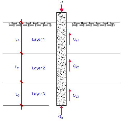
Hence ultimate pile resistance Qu;
Qu = ∑Qs + Qb —— (1)
Qs = Shaft resistance = qsAs
Qb = Base resistance = qbAb
Where qs is the unit shaft resistance of the pile and As is the surface area of the pile for which qs is applicable. Ab is the cross-sectional area of the base of the pile while qb is the base resistance.
For pile in cohesionless soil (C = 0)
Qs = q0KstanδAs —— (2)
For pile in cohesive soil (ϕ = 0)
Qs = αCuAs —— (3)
Where;
q0 is the average effective overburden pressure over the embedded depth of the pile for which Kstanδ is applicable.
Ks is the lateral earth pressure coefficient
δ is the angle of wall friction
Cu is the average undrained shear strength of clay along the shaft
α is the adhesion factor.
Typical values of δ and Ks are given in the table below;

On the other hand, the typical equations for obtaining the base resistance of a single pile are given below;
Qb = Base resistance = qbAb
Where qb is the unit base resistance of the pile and Ab is the area of the pile base.
For pile in cohesionless soil (C = 0)
Qb = q0NqAb —— (4)
For pile in cohesive soil (ϕ = 0)
Qb = cbNcAb —— (5)
For pile in c-ϕ soil;
Qb = (cbNc + q0Nq)Ab —— (6)
Where Nq and Nc are bearing capacity factors.
Therefore for a design to be considered acceptable, the applied load ≤ Ultimate Capacity/Factor of Safety. The factor of safety usually varies between 2.0 and 3.0 and depends on the quality of ground investigation carried out.
Pile Foundation Design to Eurocode 7
EN 1997-1:2004 allows the resistance of individual piles to be determined from;
- static pile formulae based on ground parameters
- direct formulae based on the results of field test
- the results of static pile load test
- the results of dynamic impact tests
- pile driving formulae, and
- wave equation analysis
According to clause 7.6.2.1 (1)P, to demonstrate that the pile foundation will support the design load with adequate safety against compressive failure, the following inequality shall be satisfied for all ultimate limit state load cases and load combinations:
Fc,d ≤ Rc,d —— (7)
Where Fc,d is the design axial load on the pile, while Rc,d is the compressive resistance of the pile. Fc,d should include the weight of the pile itself, and Rc,d should include the overburden pressure of the soil at the foundation base. However, these two items may be disregarded if they cancel approximately. They need not cancel if the downdrag is significant, or when the soil is very light, or when the pile extends above the ground surface.
For piles in group, the design resistance shall be taken as the lesser of the compressive resistance of the piles acting individually, and the compressive resistance of the piles acting as a group (block capacity). According to clause 7.6.2.1(4), the compressive resistance of the pile group acting as a block may be calculated by treating the block as a single pile of large diameter.
Static pile formulae based on ground parameters
Methods for assessing the compressive resistance of a pile foundation from ground test results shall have been established from pile load tests and from comparable experience. Generally, the compressive resistance of the pile shall be derived from;
Rc,d = Rb,d + Rs,d —— (8)
Where;
Rb,d = Rb,k/γb
Rs,d = Rs,k/γs
The values of the partial factors may be set by the National annex. The recommended values for persistent and transient situations are given in Table A6, A7, and A8 of EN 1997-1:2004 for driven, bored, and CFA piles respectively;
Table 1 (Table A6): Partial resistance factors (γR) for driven piles
| Resistance | Symbol | R1 | R2 | R3 | R4 |
| Base | γb | 1.0 | 1.1 | 1.0 | 1.3 |
| Shaft (compression) | γs | 1.0 | 1.1 | 1.0 | 1.3 |
| Total/combined (compression) | γt | 1.0 | 1.1 | 1.0 | 1.3 |
| Shaft in tension | γs;t | 1.25 | 1.15 | 1.1 | 1.6 |
Table 2 (Table A7): Partial resistance factors (γR) for bored piles
| Resistance | Symbol | R1 | R2 | R3 | R4 |
| Base | γb | 1.25 | 1.1 | 1.0 | 1.6 |
| Shaft (compression) | γs | 1.0 | 1.1 | 1.0 | 1.3 |
| Total/combined (compression) | γt | 1.15 | 1.1 | 1.0 | 1.5 |
| Shaft in tension | γs;t | 1.25 | 1.15 | 1.1 | 1.6 |
Table 3 (Table A8): Partial resistance factors (γR) for continuous flight auger (CFA) piles
| Resistance | Symbol | R1 | R2 | R3 | R4 |
| Base | γb | 1.1 | 1.1 | 1.0 | 1.45 |
| Shaft (compression) | γs | 1.0 | 1.1 | 1.0 | 1.3 |
| Total/combined (compression) | γt | 1.11 | 1.1 | 1.0 | 1.4 |
| Shaft in tension | γs;t | 1.25 | 1.15 | 1.1 | 1.6 |
The characteristic values Rb,k and Rs,k shall be determined from;
Rc,k = Rb,k + Rs,k = (Rb,cal + Rs,cal)/ξ = Rc,cal/ξ = min[Rc,cal(mean)/ξ3; Rc,cal(min)/ξ4] —— (9)
where ξ3 and ξ4 are correlation factors that depend on the number of profiles of tests, n. The values of the correlation factors may be set by the National annex. The recommended values are given in Table A10 of EN 1997-1:2004. For structures with sufficient stiffness and strength to transfer loads from “weak” to “strong” piles, the factors ξ3 and ξ4 may be divided by 1.1, provided that is never less than 1.0.

The characteristic values may be obtained by calculating:
Rb,k = Ab qb,k —— (11)
Rs,k = ∑As,i qs,i,k —— (12)
where qb,k and qs,i,k are the characteristic values of base resistance and shaft friction in the various strata, obtained from values of ground parameters.
To estimate pile shaft friction and end bearing from ground parameters, the following relationships may be applied;
Cohesionless soils;
qs,k = σv‘kstanδ —— (13)
qb,k = σv‘ Nq —— (14)
Cohesive soil or weak rock (mudstone)
qs,k = αCu —— (15)
qb,k = CuNc —— (16)
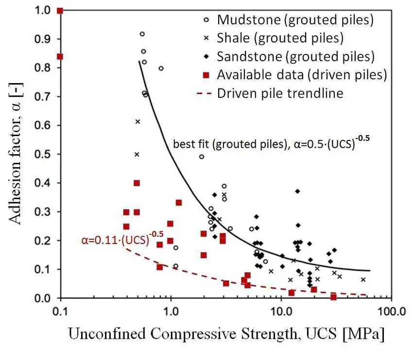
Adhesion factor (α) can be read from chart, or determined from the unconfined compression test result (UCS). For piles in clay, Nc is usually taken as 9.0.
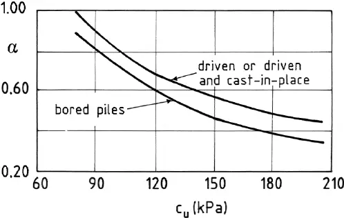
It is usually recommended that Cu < 40 kPa, α should be taken as 1.0.
Design of pile foundation using static pile load test
The procedure for determining the compressive resistance of a pile from static load tests is based on analysing the compressive resistance, Rc,m, values measured in static load tests on one or several trial piles. The trial piles must be of the same type as the piles of the foundation, and must be founded in the same stratum.
An important requirement stated in Eurocode 7 is that the interpretation of the results of the pile load tests must take into account the variability of the ground over the site and the variability due to deviation from the normal method of pile installation. In other words, there must be a careful examination of the results of the ground investigation and of the pile load test results. The results of the pile load tests might lead, for example, to different ‘homogeneous’ parts of the site being identified, each with its own particular characteristic pile compressive resistance.
To use static load test result to design pile foundation, determine the characteristic value Rc,k from the measured ground resistance Rc,m using the following equation:
Rc,k = Min{(Rc,m)mean/ξ1; (Rc,m)min/ξ2} —— (17)
where ξ1 and ξ2 are correlation factors related to the number n of piles tested, and are applied to the mean (Rc,m)mean and to the lowest (Rc,m)min of Rc,m, respectively. The recommended values for these correlation factors, given in Annex A, are intended primarily to cover the variability of the ground conditions over the site. However, they may also cover some variability due to the effects of pile installation.

The design pile compressive resistance, Rc,d is obtained by applying the partial factor γt to the total characteristic resistance or the partial factors γs and γb to the characteristic shaft resistance and characteristic base resistance, respectively, in accordance with the following equations:
Rc,d = Rc,k/γt —— (18)
or
Rc,d = Rb,k/γb + Rs,k/γs —— (19)
Rc,d for persistent and transient situations may be obtained from the results of pile load tests using DA-1 and DA-2 and the recommended values for the partial factors γt or γs and γb given in Tables A.6, A.7 and A.8 of EN 1997-1:2004.




I totally agree when you talked about the importance of careful examination when it comes to the ground and having pile load test results first before proceeding with a project. I can imagine how those findings will be important so that filing contractors will actually know what materials to use and how to push through with the project. There are probably different types of soil and properties to work which means that every client that they will have will probably have different needs on the piece of land that they have.