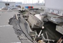
A foundation is defined as the structural component in direct contact with the ground, responsible for transferring and distributing the dead, superimposed, and live loads of a structure to the underlying soil strata. Therefore, the major function of foundations is to distribute the loads imposed by the superstructure onto the underlying ground in a manner that shear failure of the soil and excessive or differential settlement does not occur.
Due to the inherent variability of soil and rock formations, there is a need for a unique foundation design for virtually every construction project, even within close proximity. Given the exploratory nature of foundation engineering, leveraging the collective knowledge from conferences, academic publications, and codified literature is very important.
Furthermore, by synthesizing experience from previous jobs, comparative analyses of similar projects, and site-specific geotechnical data, engineers can exercise sound judgment in developing cost-effective, buildable, and safe substructure solutions.
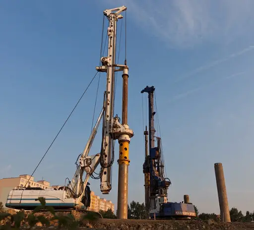
Superstructure loads are transmitted to the soil through columns or wall elements. These column or wall elements typically possess high compressive strength (250-350 N/mm² for steel and ≥ 15 N/mm² for concrete) and consequently, relatively small cross-sectional areas.
Conversely, soil exhibits significantly lower bearing capacities, ranging from 150 to 250 kPa (0.15 – 0.25 N/mm2), often several hundred times less than the column material. To prevent soil failure and excessive deformation, foundation systems must effectively distribute column loads across the soil interface.
To ensure the best performance of a civil engineering structure, the foundation, substructure, and superstructure must be considered as an integrated system. The permissible total and differential settlements are contingent upon the structure’s intended use, occupancy, and contextual relationship to adjacent structures and topography. Economic considerations and constructability must also be prioritized in foundation design to avoid unforeseen delays and cost overruns.
The selection of an optimal foundation system presents a significant challenge within the design and construction industry. Arguably, this decision constitutes one of the most critical stages of the design process. The foundation is undeniably the primordial element of any structure, as it provides the essential support system.
Any failure of the foundation is likely to compromise the integrity of the entire superstructure, and remedial measures are often prohibitively expensive. Consequently, careful consideration of the most suitable foundation type and configuration must be undertaken during the preliminary design phase.
The selection of a foundation system for any kind of structure involves a comprehensive evaluation of several critical factors, including sub-soil conditions, historical land use, adjacent structures, project scale, construction timeline, and budgetary constraints. A thorough site investigation is indispensable in assessing these parameters.
This article will focus on the different configurations and classifications of foundations, elucidating the criteria governing their selection. Fundamental terminology, functional attributes, constituent materials, and behavioural characteristics will be defined.
Types of Foundation
Foundations are generically categorized into two distinct groups:
- Shallow foundations, and
- Deep foundations
Shallow Foundations
British Standard 8004 categorizes foundations as shallow if their depth from the finished ground level is less than 3 metres. This classification encompasses strip, pad, raft foundations, etc. It is important to note that the 3-metre depth criterion is arbitrary, and foundations with a disproportionately high depth-to-breadth ratio may require design considerations typically associated with deep foundations. For shallow foundations, the depth is generally Df/B ≤ 2.5.
Shallow foundations function by spreading heavy structural loads laterally to the underlying soil, hence the term “spread footing.” While a spread footing supports a single column, a mat foundation is a wider base designed to accommodate multiple columns, either randomly or in rows.
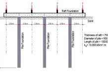
In some cases, a mat foundation may be further supported by piles or drilled piers (piled-raft foundation). Structures such as machinery often exert concentrated loads, necessitating a base to distribute these forces similarly to a footing.
The prominent examples of shallow foundations are;
- Pad foundation
- Raft foundation
- Strip foundation
- Combined footing
- Strap footing
- Continuous beam and slab footing
Pad Foundation
Pad foundations are typically employed to support single structural columns. These foundations commonly consist of planar concrete slabs with circular, square, or rectangular geometries and uniform thickness. To accommodate heavier column loads, the pad foundation may be stepped or thickened, facilitating load dispersion. In cases where structural steel columns impose exceptionally high loads, steel grillages are often integrated into the pad foundation to enhance load distribution and capacity.
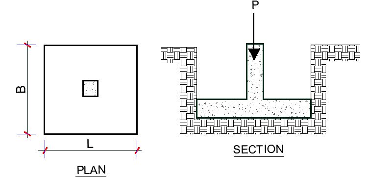
The basis for the design of pad foundation is ensuring that the pressure transferred to the soil from the footing (q = P/BL) is less than the allowable bearing capacity of the soil. This is followed by the provision of adequate footing thickness and reinforcements to resist bending moments, diagonal shear, and punching shear as a result of the column load.
In some cases, pad foundations can be unreinforced. Plain concrete pad footings, also referred to as mass concrete pad footings, are employed to support low-concentrated loads from columns and posts. Similar to plain concrete strips, it is commonly assumed that load dispersion occurs at a 45-degree angle. These foundations offer economic advantages when excavation sides can be utilized as formwork and sufficient depth can be achieved without requiring reinforcement.
Raft Foundation
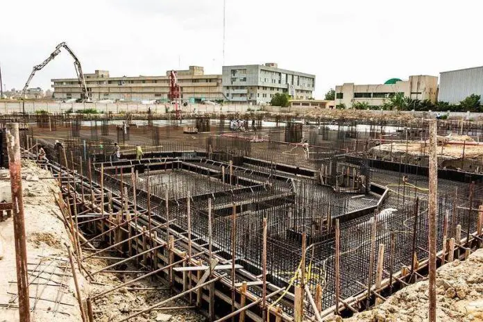
A raft foundation is a large, reinforced concrete slab that covers the entire footprint of a building or a significant portion of it and is used to support a group of columns or walls. It acts as a single, flat base that distributes the building’s weight evenly over a wide area of soil.
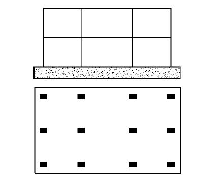
There are different types of raft foundations such as flat raft foundation, beam and slab raft foundation (beams may be upstand or downstand, cellular raft foundation, buoyancy raft foundation, and crust raft foundation.
Flat Raft Foundation
The flat raft foundation is the simplest type of raft foundation. It consists of a reinforced concrete slab of uniform thickness that covers the entire footprint of a building. This slab distributes the building’s load evenly across the ground. It is uneconomical when the columns are widely spaced and when loads are very heavy.
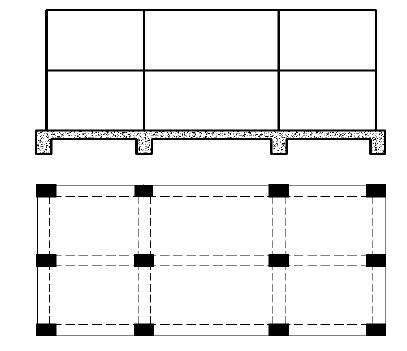
Beam and slab raft foundation
Beam and slab raft foundation comprises ground-bearing beams arranged in two or more directions to support concentrated superstructure loads. These beams are interconnected by a ground-bearing slab supported on compacted fill material.
This foundation type is particularly suitable for structures subjected to heavy loads, necessitating the incorporation of stiffening beams along primary load paths. The monolithic integration of slab and beams mitigates lateral distortions and differential settlements. Design calculations for the slab and beams are conducted independently before the final structural analysis.
Cellular raft foundation
A cellular raft foundation comprises a network of interconnected, two-way beams positioned between an upper suspended slab and a lower ground-bearing slab. This configuration is typically employed in scenarios where the structure imposes exceptionally heavy concentrated loads on suboptimal soil conditions.
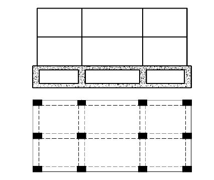
A primary advantage of cellular rafts is the substantial increase in bearing capacity achieved through overburden removal. The voids created by the cellular structure can be repurposed for various utilities, including habitable spaces, storage, or infrastructure installation. This foundation type is particularly suited to regions prone to seismic activity or those impacted by mining operations. Despite these benefits, the high construction costs associated with cellular rafts limit their widespread application.
Buoyancy Raft Foundation
Buoyancy raft foundations, also known as compensated foundations or deep cellular rafts, are a type of floating foundation. They are employed in extreme conditions where soil bearing capacity is exceptionally low and the expected settlement of the structure would be excessive.
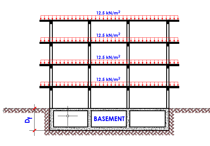
The concept involves excavating soil beneath the foundation to a depth where the weight of the removed soil is equal to the combined weight of the structure and the foundation itself. This effectively creates a “floating” foundation.
Crust Raft Foundation
A crust raft foundation is a type of raft foundation that incorporates thicker sections of concrete around the edges and columns to increase its structural capacity. It’s essentially a reinforced concrete slab with nominal thickenings around the columns and slab edges.
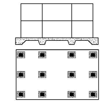
Strip Foundation
Strip foundations are typically employed to support load-bearing walls and closely spaced columns where the proximity of individual pad foundations would render them impractical. Excavating and concreting a continuous strip foundation is generally more cost-effective than constructing numerous isolated pad foundations.
Strip foundations are often considered economically advantageous when the spacing between adjacent square pads is less than their dimensions. To facilitate construction, closely spaced pad foundations can be created by incorporating vertical joints within a monolithic concrete strip.
Concrete strips can be classified into two primary categories: plain concrete strips and reinforced concrete strips, commonly referred to as wide strip footings. In the case of plain concrete strips, the thickness is dictated by the necessary dispersion angle to intersect the footing’s edge.
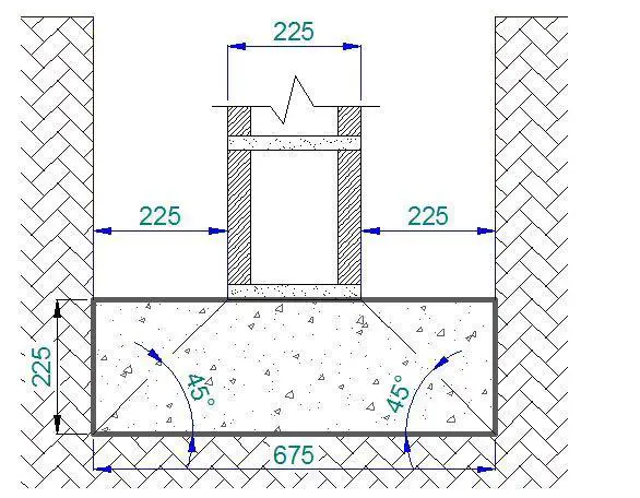
Based on this principle, the width of a plain concrete strip footing is conventionally established as three times the thickness of the supported masonry wall. Conversely, the strip footing thickness is typically equivalent to the masonry wall thickness. Consequently, a 225mm thick masonry wall would necessitate a 675mm wide and 225mm thick strip footing.
Wide strip foundations are necessary when soil-bearing capacity is insufficient to support a narrower foundation. Under these conditions, the foundation width increases, necessitating reinforcement to counteract transverse bending stresses within the extended portions of the concrete strip.
Combined Footing
A combined footing is a type of foundation designed to support multiple columns when they are situated closely together such that individual isolated footings would overlap or be impractical. This foundation distributes the load from these columns over a larger area of soil, reducing the ground pressure and preventing excessive settlement.
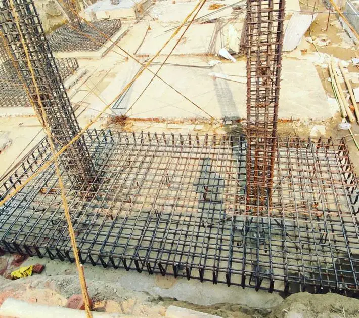
Combined footings are typically employed when soil bearing capacity is low, or when architectural or site constraints necessitate the close spacing of columns. They are often more economical than constructing multiple isolated footings in such situations.
Combined footings are typically designed as balanced footings, with cantilever extensions adjusted to align the resultant load with the footing’s centroid. In instances where geometric constraints limit footing dimensions, the resulting eccentricity must be determined and incorporated into the design calculations.
Strap Footing
Strap footings are employed when the positioning of an external column is restricted by property or site boundaries, preventing its foundation from extending beyond a specific line. This configuration involves a connecting beam, or strap, linking the external column’s footing to the nearest internal column footing. The primary function of the strap is to counteract the overturning moment induced by the eccentric loading on the external footing.
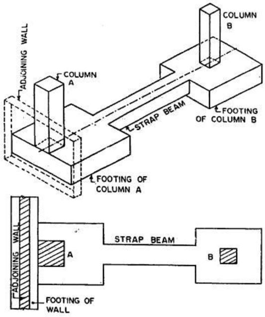
The primary function of the strap beam is to prevent the outer footing from overturning due to the eccentric loading caused by the column’s proximity to the property line. It transfers the load from the outer footing to the inner footing, ensuring stability and preventing differential settlement.
Continuous beam and slab footing
A continuous beam and slab footing is a foundation system composed of interconnected beams and a concrete slab. It is typically used to support multiple columns in a linear arrangement. The beams distribute the column loads to the slab, which in turn transfers the load to the soil.
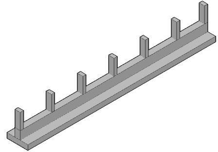
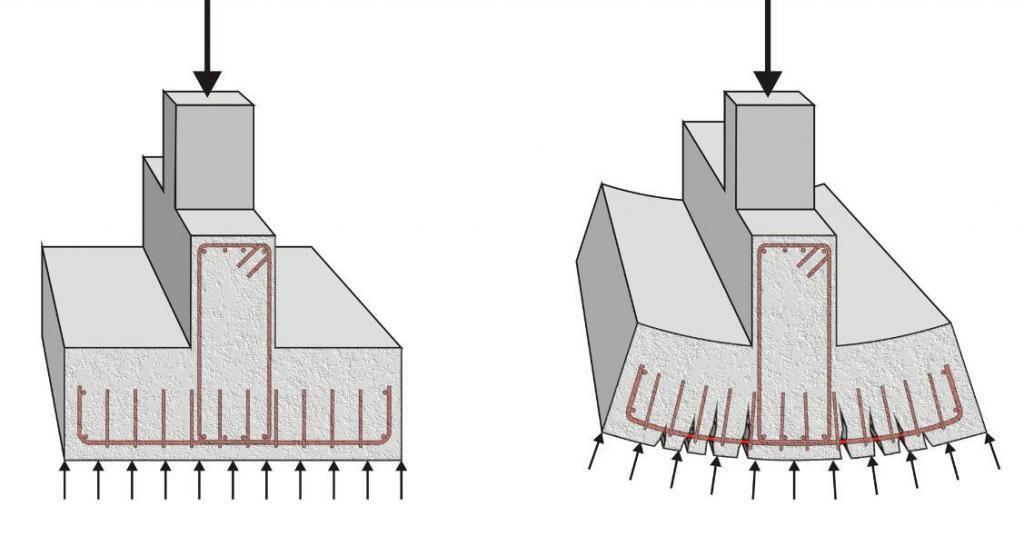
This type of footing is often employed when columns are closely spaced, and individual pad foundations would be impractical or uneconomical. The continuous nature of the beam and slab system provides increased structural stability and helps to distribute loads evenly over a larger area, reducing the potential for differential settlement.
Deep Foundation
Deep foundations are required to carry loads from a structure through weak compressible soils or fills onto stronger and less compressible soils or rocks at depth, or for functional reasons. The typical examples of deep foundations are piles, caissons, drilled piers, or drilled caissons. For deep foundations, it is typical that Lp/B ≥ 4+.
Pile Foundation
A pile foundation is a deep foundation system consisting of long, slender columns driven or cast into the ground to support structural loads. These columns, typically made of concrete, steel, or timber, transfer the building’s weight to a stronger soil layer or bedrock at depth.
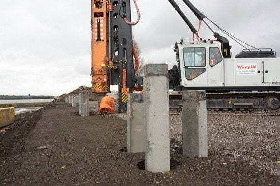
Bearing piles are required where the soil at normal foundation level cannot support ordinary pad, strip, or raft foundations or where structures are sited on deep filling which is compressible and settling under its own weight. Piled foundations
are a convenient method of supporting structures built over water or where uplift loads must be resisted. Inclined or raking piles are provided to resist lateral forces.
Pile foundations are employed in various scenarios, including:
- Weak soil conditions: When the upper soil layers cannot support the building’s load.
- Large loads: For heavy structures like high-rise buildings or bridges.
- Waterlogged or soft ground: In areas with high water tables or soft soil.
- Slope stability: To prevent slope failures or landslides.
There are several types of piles, each with specific applications, including:
Driven piles: Precast concrete or steel piles hammered into the ground.
Cast-in-place piles: Concrete poured into drilled holes in the ground.
Bored piles: Large-diameter piles created by drilling and filling with concrete.
The choice of pile type depends on factors such as soil conditions, load capacity requirements, and construction constraints.
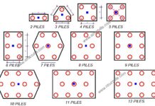
Piles are usually provided in groups. A pile group is a cluster of individual piles acting together to support a structural load. When a single pile cannot adequately carry the load, multiple piles are installed in a specific arrangement to form a group. The arrangement and spacing of piles within a group significantly influence the overall load-carrying capacity and behaviour of the foundation.
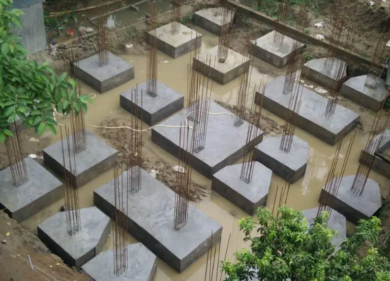
A pile cap is a reinforced concrete slab or block placed on top of a group of piles to distribute the load from a column or wall to the individual piles. It acts as a structural element to connect the piles and ensure uniform load transfer. The pile cap is designed to be rigid to distribute loads evenly among the piles and prevent differential settlement.
Caissons
A caisson foundation is a large, hollow, box-like structure used in construction to create a stable base for structures in challenging soil conditions, such as underwater or soft ground. It involves sinking a prefabricated or constructed-in-place chamber into the ground until it reaches a suitable bearing stratum.
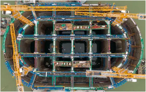
There are primarily three types of caissons:
Open Caissons: These are open at both the top and bottom, equipped with a cutting edge. As the caisson is sunk, soil is excavated from the inside, allowing it to penetrate deeper into the ground.
Closed Caissons: These are sealed at the bottom, with air or water pressure used to expel water and soil during sinking. They are often used in underwater conditions.
Pneumatic caissons: A pneumatic caisson is a specialized type of caisson that utilizes compressed air to create a dry working environment within the structure during construction. It is typically employed in underwater or waterlogged conditions where soil excavation and foundation construction would otherwise be impossible.
Drilled Pier/Shaft Foundation
A drilled pier shaft foundation, also known as a drilled shaft, is a type of deep foundation constructed by excavating a cylindrical hole in the ground and then filling it with concrete.
The shaft of drilled piers typically have a large diameter that is greater than 750 mm, and they transfer load mainly through end bearing. This is unlike pile foundations that will transfer load through skin friction and end-bearing. Pile foundations are established at great depths, whereas Pier foundations are generally shallower in depth.
Drilled piers are used when the upper soil layers are unable to support the weight of a structure, or when there are issues like expansive soils, groundwater, or seismic activity.

