Bridge pile caps are substructure elements that are used for transferring bridge superstructure load to the pile foundation. Pile caps for bridges are used for supporting the piers and/or the abutments of a bridge and are usually subjected to axial compression, shear (lateral force), and bending moment from the bridge pier or abutment.
These actions are usually resulting from the self-weight and superimposed dead loads on the bridge (permanent actions), vertical traffic live loads, horizontal actions due to wind, bridge deck contraction, impact/collision, braking, and skidding loads, etc.
Pile caps behave like thick plates and traditionally can be analysed using strut-and-tie or bending analogy method. Alternatively, finite element analysis can be used for the analysis of pile caps with or without the effects of soil-structure interaction.
It is possible to model pile caps using plates and beams on elements on Staad Pro software and obtain accurate results. Ubani has demonstrated the application of Staad Pro in the modelling of triangular pile caps (3 piles) and rectangular pile caps (2 piles) and compared the results with solutions from classical analysis methods. The results were found to be satisfactory for design purposes. The aim of this article is to extend the analysis of pile caps using Staad Pro to bridges and other complex structures (see the previous articles below).
Comparative analysis of triangular pile cap using Staad Pro and bending theory
Structural design of pile caps using strut-and-tie method
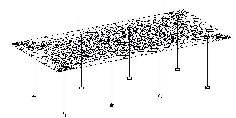
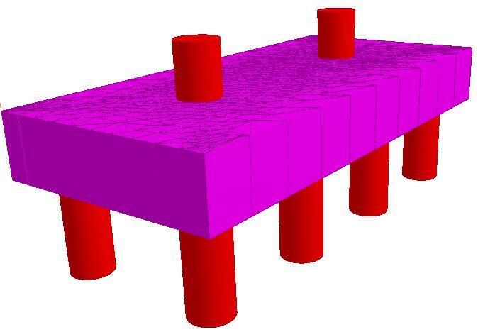
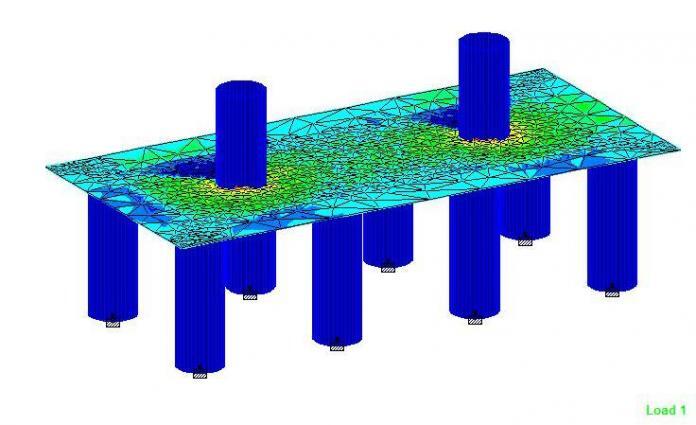
In order to achieve this, the pile cap should be modelled using plate elements, while the piers (columns) and piles should be modelled using beam elements. In the case of pile caps supporting abutments, the abutment walls should be modelled using plate elements. It is very typical to model the piers/columns as stubs, and the actions applied to them as appropriate. The piles should be modelled as short columns that are supported with fixed supports. Furthermore, it is very important to ensure that all the nodes in the model are interconnected and rigid.
To demonstrate how this can be done, let us consider the pile cap of a bridge pier shown below. Note that the arrangement of the piles and pile caps should be consistent with the standard practice of ensuring that the maximum spacing of piles (for friction piles) should not less 3 times the diameter of the piles. The selection of the size and number of piles should be based on the geotechnical soil test report and the summation of the service loads from the superstructure.
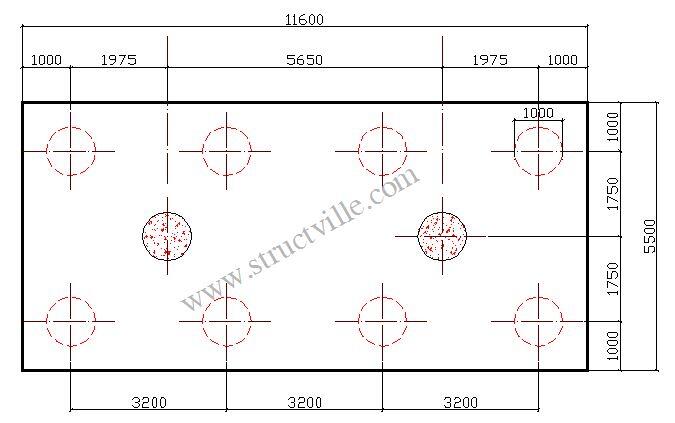
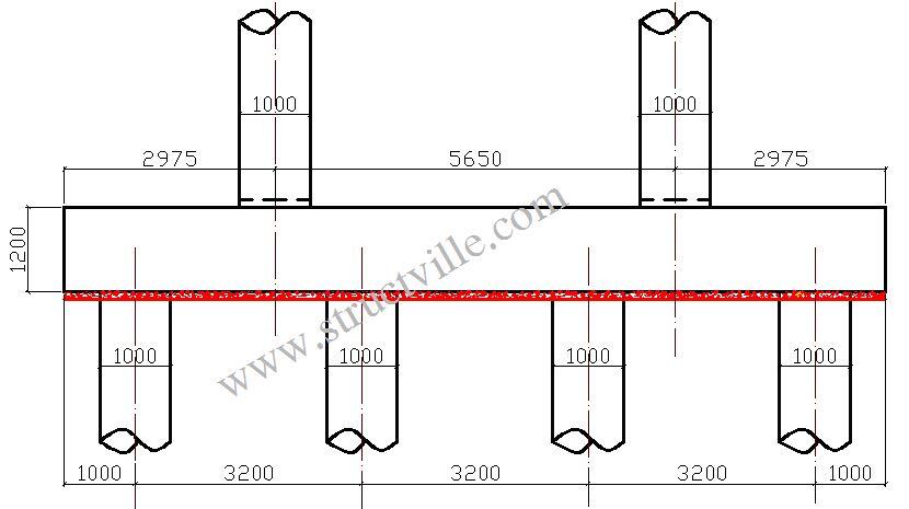
For the bridge substructure shown above, the actions on each leg of the pier are as follows;
Load Combinations
Vertical actions
(ULS) = 1.35Gk + 1.35Qk = 4560 kN
(SLS) = 1.0Gk + 1.15Qk = 3378 kN
Horizontal Loads
For road bridges, wind load need not be combined with braking/acceleration forces. Furthermore, accidental actions (collision) need not be considered with wind loads.
(ULS) = 620 kN
(SLS) = 496 kN
Bending moment;
(ULS) = 2412 kNm
(SLS) = 1647 kNm
The modelling of the pile cap on Staad Pro is shown below;
The reactions on the piles at SLS are shown below;
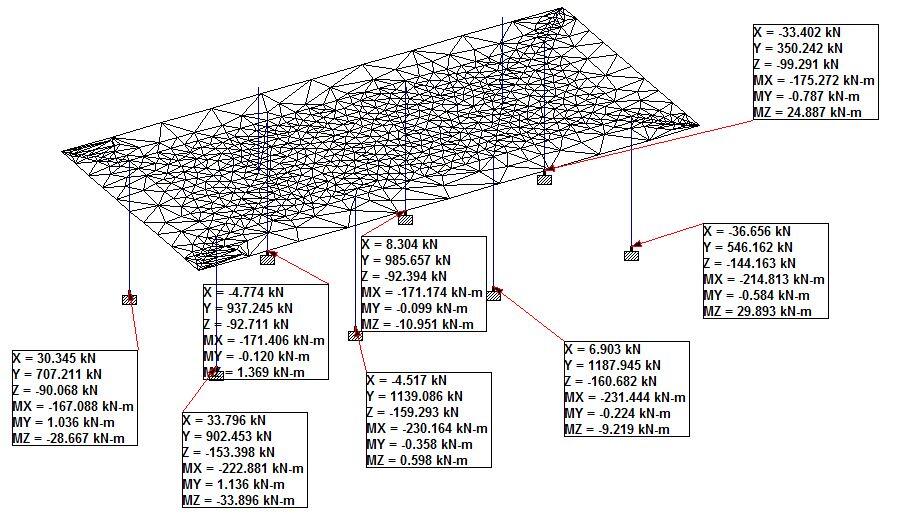
From the result above, the engineer should ensure that safe load bearing capacity of the each pile is not less than the maximum reaction on the pile (which is 1187.945 kN).
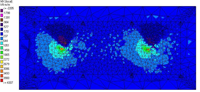
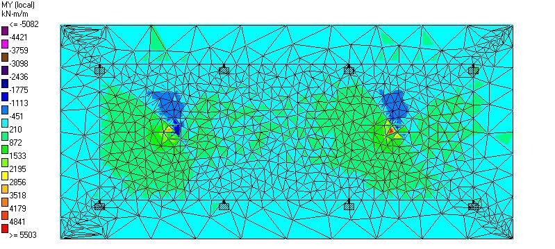
The bending moment on the pile cap at ultimate limit state is shown below;
The maximum reactions on the piles at ULS (for the sake of punching shear verification) is shown below;
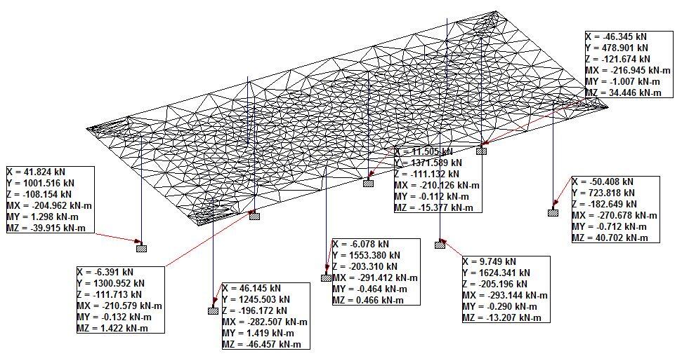
The maximum reaction is 1624.341 kN and can be used for shear verification.





An advance article for structural engineer
Could you please share the staad file to study your model? Thanks.