Trusses are important civil engineering structures that are used in the construction of roofs of buildings, bridges, towers, stadiums, etc. The main structural feature of trusses is that they are arranged in such a manner that they form triangulated systems that resist loads mainly by developing axial forces. The axial forces in the truss members may be tensile or compressive and will lead to the global deflection of the truss.
The configuration or arrangement of the members in a roof truss significantly affects the structural behaviour of the truss. This includes the distribution of the internal stresses and deflection behaviour. Some different types of trusses have been identified based on their shape and internal members’ arrangement. Examples of such are Howe truss, Fink truss, Pratt truss, K-Truss, Warren Truss, Warren truss with verticals, Baltimore Truss, etc. In this article, the effect of member configuration on the deflection behaviour of trusses was studied.
Theoretically, the factors that affect the deflection behaviour of trusses are;
- Member section and properties (Modulus of elasticity and cross-sectional area)
- Individual length of members
- Nature and magnitude of internal stresses in each member
However, in practice, it has been observed that factors such as connection details, size of holes for bolts, eccentricity of connection, etc can significantly affect the deflection value observed in roof trusses.
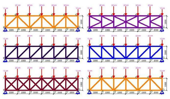
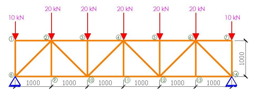
In order to achieve this, a 6m span truss was modelled on Staad Pro software and subjected to different member configurations. A constant nodal spacing of 1 m and section property of UA 90 x 90 x 10 were maintained for all the models in the study. All internal loads nodes were subjected to a concentrated load of 20 kN while the end nodes were subjected to a concentrated load of 10 kN. The typical truss configuration, loading, dimensions, and node numbering is shown below;
The analysis results are shown below;
Truss Type 1: Pratt Truss (Non-Parallel Diagonals)
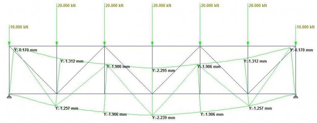
Truss Type 1 is a typical Pratt truss that is balanced in symmetry and in loading, with non-parallel diagonals in the LHS and RHS of the structure. As expected, the maximum deflection occurred at the centre with a value of 2.239 mm as shown in Figure 2. The maximum compressive forces occurred at the middle of the top chord between members 3-4 and 4-5 as shown in Figure 3. Members 3-10 and 5-10 were observed to be zero-force members. The bottom chord members between nodes 9-13 were observed to be in tension, but the entire top chord members were observed to be in compression. The general compressive to tensile member ratio was observed to be 1.5, while the web compressive to tensile member ratio was observed to be 1.16.

Truss Type 2: Parallel Flat Truss
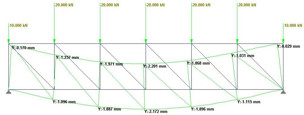
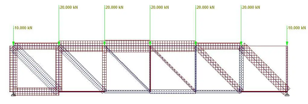
Truss Type 2 is a typical parallel flat truss comprising of verticals and diagonals that are all parallel to each other. By implication, the truss is not symmetrical in arrangement and the maximum deflection at the bottom chord occurred at the centre with a value of 2.172 mm (see Figure 4). The maximum compressive forces occurred at the top chord, while the maximum tensile forces occurred at the diagonals as shown in Figure 5. The general compressive to tensile member ratio was observed to be 2.0. In the web, the compressive to tensile member ratio was observed to be 1.6.
Truss Type 3: Pratt Truss (Parallel Diagonals)
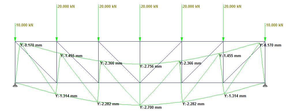
Truss Type 3 is a typical perfect Pratt truss with parallel diagonals on the LHS and RHS of the structure. The value of the maximum deflection on the bottom chord was observed to be 2.7 mm as shown in Figure 6. All the diagonals are in tension, while the verticals are in compression (see Figure 7). Furthermore, the entire top chord is in compression while the mid-span of the bottom chord is in tension. The general compression to tensile member ratio is 1.6, while the web compressive to tensile member ratio is 1.16.

Truss Type 4: Howe Truss
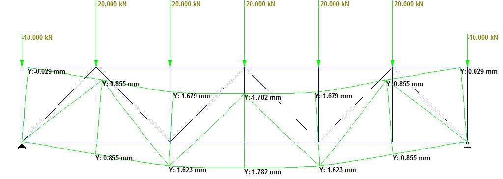
Truss type 4 is a typical Howe truss with a non-parallel diagonal arrangement. The maximum deflection on the bottom chord was observed to be 1.782 mm as shown in Figure 8. Five (5) out of the twenty-five (25) members in the truss were observed to be zero-force members (see Figure 9). Furthermore, the general compressive to tensile member ratio was observed to be 4.0, while the web compressive to tensile member ratio was observed to be to be 4.0 also.

Truss Type 5: Long Truss
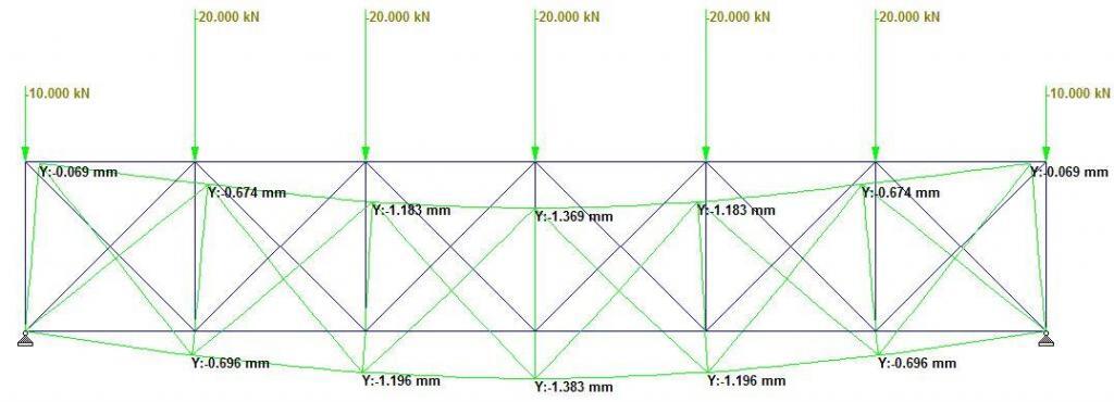
In Truss Type 5, additional internal members were introduced in the truss to form a typical Long Truss. A lower deflection value of 1.383 mm was observed at the centre of the roof truss as shown in Figure 9. This can be attributed to the additional constraints at the nodes of the trusses. The top chords are in compression (see Figure 11), and the general compressive to tensile member ratio was observed to be 1.5. In the web, a compressive to tensile member ratio of 1.11 was observed.

Truss Type 6: K-Truss
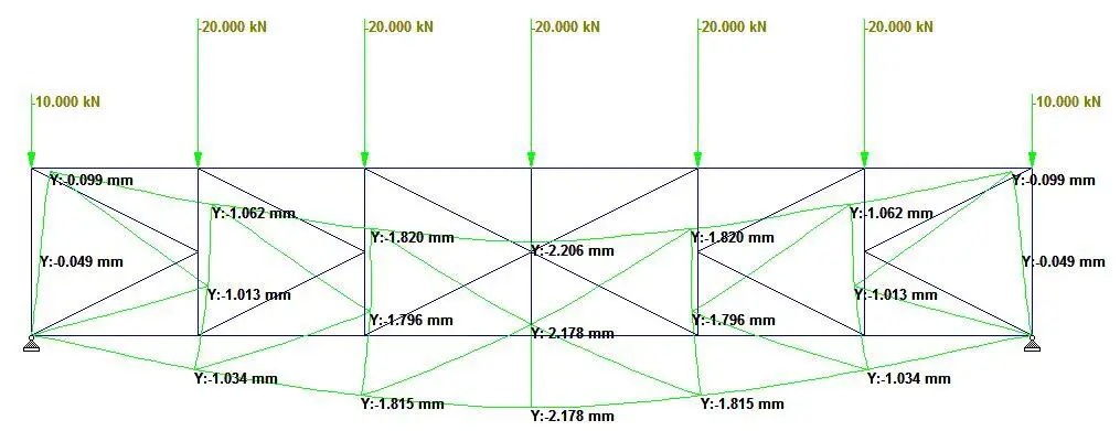
Truss type 6 is a typical K-truss. Despite having additional members, a deflection value of 2.178 mm was observed at the midspan as shown in Figure 12. Under gravity loading, a variation of axial stress distribution from compressive to tensile was observed in the vertical members (see Figure 13). A general compressive to tensile member ratio of 2.3 was observed in the truss, while the web’s compressive to tensile member ratio was 1.875.

Truss Type 7: Bailey Truss
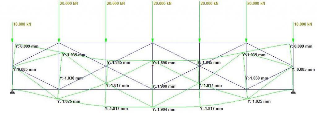
Truss type 7 is a typical Bailey Truss. The deflection at the midspan was observed to be 1.904 mm (see Figure 14). A little consideration shows that a significant number of members can be removed without affecting the behavior of the truss as shown in Figure 15. A general compressive to tensile member ratio of 2.25 was observed in the truss, while a compressive to tensile member ratio of 3 was observed in the web.

Truss Type 8: Bailey Truss (with K at mid-span)
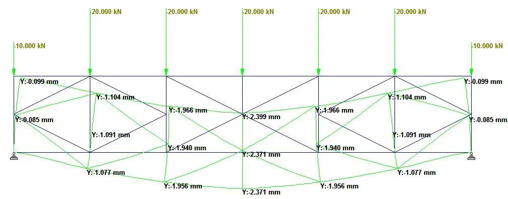
Truss Type 8 is a typical Bailey truss but with a K-configuration at the midspan. This configuration had a larger deflection than a pure K-truss or Bailey Truss arrangement. The maximum deflection observed in the truss was 2.371 mm as shown in Figure 16. A general compressive to tensile member ratio of 2.1 was observed in the truss, while a compressive to tensile member ratio of 2.83 was observed in the web (see Figure 17).

The summary of the findings is shown in the Table below;
| Truss Type | Maximum deflection (mm) | C/T ratio (general) | C/T ratio (web) |
| Truss Type 1: Pratt Truss (Non-Parallel Diagonals) | 2.239 | 1.5 | 1.16 |
| Truss Type 2: Parallel Flat Truss | 2.172 | 2.0 | 1.6 |
| Truss Type 3: Pratt Truss (Parallel Diagonals) | 2.700 | 1.6 | 1.16 |
| Truss Type 4: Howe Truss | 1.782 | 4.0 | 4.0 |
| Truss Type 5: Long Truss | 1.383 | 1.5 | 1.11 |
| Truss Type 6: K-Truss | 2.178 | 2.3 | 1.875 |
| Truss Type 7: Bailey Truss | 1.904 | 2.25 | 3.0 |
| Truss Type 8: Bailey Truss (with K at mid-span) | 2.371 | 2.1 | 2.83 |
The variation of vertical deflection with type of truss is shown in Figure 18.
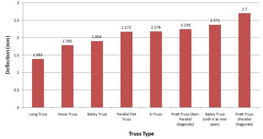
From the result, the lowest deflection was observed in the Long Truss (Truss Type 5) due to the additional constraints that reduced the degree of movement at the nodes. The lowest deflection value occurred at the expense of additional members and increased fabrication cost. The most economical configuration in terms of deflection can be deemed to be the Howe Truss, which offered the lowest deflection with minimal members. The ratio of the number of compressive to tensile members did not have any recognisable effect on the deflection behaviour of trusses.

