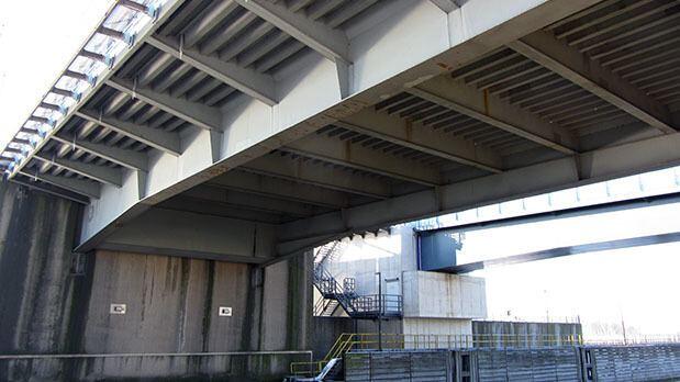
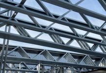
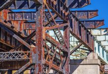
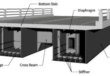
An orthotropic steel deck bridge is made up of a steel plate with welded stiffeners running in opposite directions. Longitudinal stiffeners are known as ribs, and transversal stiffeners are known as cross beams or floor beams. The entire deck is supported by main girders running longitudinally. The presence of two different members in the two orthogonal directions means that the stiffness of the deck is anisotropic (not the same in every direction). The term ‘orthotropic’ is coined from orthogonal-anisotropic.
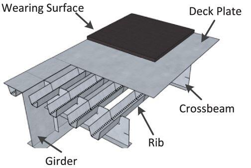
The major structural components of an orthotropic steel deck are;
- The wearing surface
- The deck plate
- The transverse stiffeners
- The longitudinal stiffeners (ribs), and
- The main girders
Because the deck serves as a top flange for the longitudinal and transversal stiffeners, as well as the major girders, the orthotropic steel deck is a cost-effective and efficient system. This concept saves material, reduces self-weight, and increases the rigidity of the deck at the same time (Håkansson and Wallerman, 2015).
Structural Behaviour of Orthotropic Steel Deck
Almost every structure that exists is made up of several structural elements such as beams, columns, and slabs. In a sophisticated way, those elements contribute to the overall behavior of the structure, however, it is common for these members to be isolated and designed individually.
The elements of orthotropic steel deck bridges are linked in a more complicated way, and the same structural elements can perform several functions. The plate functions as a load distributer between the ribs as well as a top flange for ribs, crossbeams, and main girders, as previously stated. Due to this complex interaction, individual members should not be designed in isolation from each other. In other words, the structural elements cannot be treated individually if the true response of the bridge must be known (Håkansson and Wallerman, 2015).
The diagram below depicts the transfer of a concentrated load to the major girders. The load is applied to the deck plate, which distributes it among the ribs. The load is transferred from the ribs to the cross beams, which are then distributed between the main longitudinal girders.

Subsystems for Analysis of Orthotropic Steel Deck Bridges
It has been proposed that the entire bridge deck be broken into subsystems in order to make hand computations and characterize the complex structural behavior of orthotropic steel decks. Because these subsystems are believed to work independently of one another, the impacts of the several subsystems can be combined using superposition (US Department of Transportation, 2012).
The proposed subsystems are described below;
Subsystem 1: Local Plate Deformation
In this subsystem, the deck plate should only transfer the imparted wheel load to the adjacent rib walls (US Department of Transportation, 2012). Deck plate bending is used to transfer the load. When a concentrated force is applied over a rib, the deck plate deforms as shown in Figure 3.

Subsystem 2: Panel Deformation
Due to the fact that ribs share the same top flange, they are unable to operate independently, resulting in panel deformation. As explained in the preceding section, a concentrated force applied to the deck plate will be transferred to the neighboring ribs, but because of the shared top flange, even ribs that are not loaded will deflect. This action reduces the stresses in loaded ribs while increasing stresses in unloaded ribs (US Department of Transportation, 2012). Figure 4 shows how the panel deforms as a whole, with all ribs deflecting at the same time.

Subsystem 3: Longitudinal Flexure of the Ribs
Ribs are constructed in a continuous pattern over cross beams, and the fact that cross beams deflect under load must be taken into account. The ribs are treated as continuous across discrete flexible supports to account for this flexure. Cross-beams are simply supported between rigid main girders in this concept, and they deflect when loaded.
Subsystem 4: Cross Beam In-plane Bending
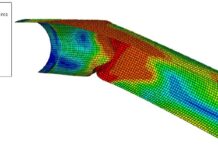
The ribs are built in a continuous pattern over the cross beams, as previously stated. This will result in cut-outs in the cross-section of the cross beam where the rib passes through. As a result, the geometry of the cross beam will change, making hand computations of in-plane stresses from bending and shear more difficult. According to the US Department of Transportation (2012), FE-analysis should be used to simulate the entire cross beam. The deformed shape of a cross beam subjected to in-plane forces is seen in Figure 5.

Subsystem 5: Cross beam distortion
Three separate effects affect the local stresses in the cross beam at the cross beam and rib intersection. Out-of-plane distortion from rib bending, distortion of rib walls due to shear stresses, and distortion of ribs due to unequal deflection are the local mechanisms at these intersections.
Subsystem 6: Rib Distortion
The rib will twist about its rotating centre if a concentrated force is applied in the mid-span between two cross beams and is eccentric about the axis of the rib (US Department of transportation, 2012). Because the rib-cross beam junction will be a fixed or partially fixed barrier, depending on how large cut-outs are employed, there will be substantial stress concentrations in the welds where twisting is inhibited. When the ribs are loaded, they distort as shown in Figure 6.

Subsystem 7: Global Behaviour
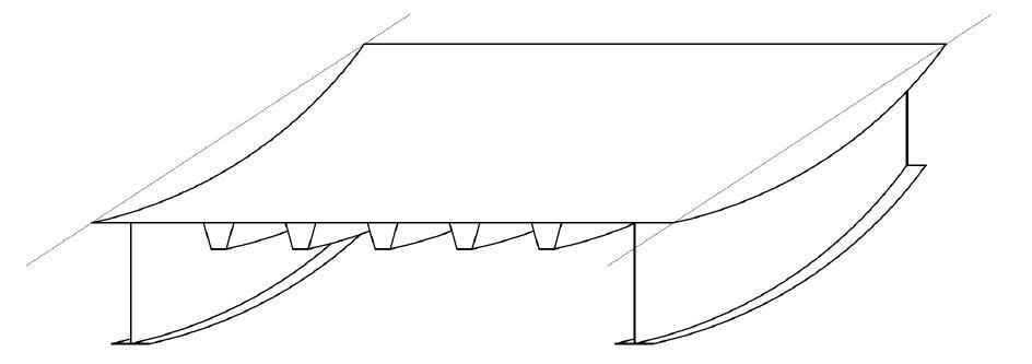
When there is no consideration for local effects, the global system explains the displacement of the main girders as well as the overall behavior. It is possible to determine stresses and strains in the structure using traditional methods in this system (US Department of Transportation, 2012). Figure 7 depicts the orthotropic steel deck bridge’s global bending.
References
(1) Håkansson J. and Wallerman H. (2015): Finite Element Design of Orthotropic Steel Bridge Decks. Masters Thesis submitted toChalmers University of Technology, Göteborg, Sweden
(2) Karlsson A. and Wesley C. (2015): Necessity of Advanced Fatigue Analysis for Orthotropic Steel Deck Bridges. Chalmers University of Technology, Göteborg, Sweden
(3) US Department of Transportation (2012): Manual for Design, Construction, and Maintenance of Orthotropic Steel Deck Bridge. US Department of Transportation, Federal Highway Administration, Publication no. FHWA-IF-12-027. USA

