Lattice truss structural systems have been employed in constructing railway and highway bridges with great success for so many years. The design of truss bridges involves the analysis of the structure to obtain the internal forces due to moving traffic and permanent loads (self-weight), selection of adequate steel members, design of the connections, and check for fatigue. The availability of numerous commercial design software has made the analysis and design of 3D truss bridges easier than it was in the past.
The Warren truss, the Modified Warren truss, and the Pratt truss are the three major truss configurations in use today, and they can all be employed as an underslung truss, a semi-through truss, or a through truss bridge.
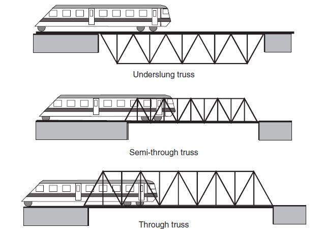
In an underslung truss, the live loading caused by the passage of automobiles or trains is carried directly by the top chord. In situations where the depth of construction or clearance under the bridge is not critical, underslung trusses can be conveniently used.
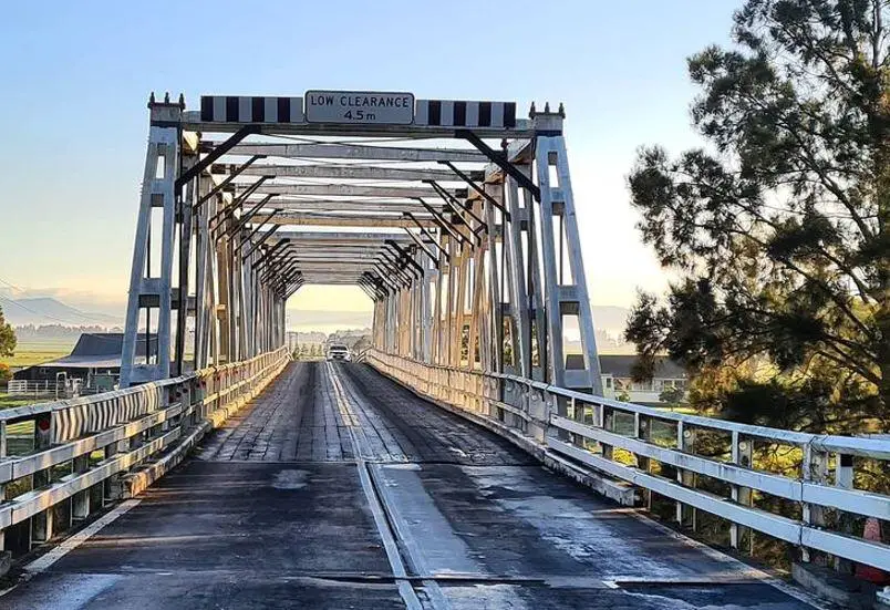
In semi-through trusses, vehicles travel on the bottom chord of the truss, but the transient live load projects above the top chord members due to the height of the vehicles relative to the top chord of the truss. As a result, the top chords in semi-through trusses cannot be braced laterally, and these chord elements must rely on U-frame action for lateral stability. However in a through truss bridge, vehicles travel through the centre of the bridge on the bottom chord, and the space between the live load and the top chords is sufficient that the top chord members can be braced laterally. Through truss bridge appears to be the most common type of truss bridge.
Internal Forces in Truss Bridges
The members of a truss bridge will predominantly carry axial tension or axial compression stresses if the structure is designed and detailed so that live loading is effectively applied at the nodes. The global bending moment acting on the bridge may be resolved into a couple made up of the compression forces in the top chord and axial tension forces in the bottom chord. Similarly, the diagonal web elements carry the global shear force exerted on the truss bridge, either in axial tension or compression, depending on the configuration of the truss.
As an example, the diagonal web elements of a Warren truss alternately carry compression and tension over the bridge. The internal diagonal web members of a Pratt truss, on the other hand, are all loaded in tension, while the shorter vertical web members are loaded in compression.
Members of Truss Bridges
The chords and web members of truss bridges can be made out of a variety of steel sections. For the tension and compression chords as well as the web members of short-span (30–50 m) highway trusses, rolled “H” sections and square hollow sections are suitable. Larger fabricated sections, such as a “top hat” section or box section, will be needed for the chords of longer highway truss bridges or trusses bearing railway loads.

Analysis of Truss Bridges
Truss bridges transmit imposed loads to the foundations through the axial tension and compression forces in the members. Therefore, these structures can be analyzed as pin-jointed members, either as a two-dimensional truss or, more preferably, as a three-dimensional space truss.
This form of analysis assumes that member connections are pinned, which means that none of the truss members may attract moment or torsion. By hand, a two-dimensional plane truss analysis can be solved by utilizing equilibrium equations to resolve the forces at each joint in turn, or by employing the method of sections to free-body segments of the bridge truss, again using equilibrium equations to derive member forces.
The stiffness method can also be used to calculate node displacements first, and then member forces. Nowadays, truss bridges do not have pinned joints; instead, the connections are welded or bolted; yet, analyzing the structure as a two- or three-dimensional pin-jointed assembly allows for an accurate assessment of member axial stresses but overpredicts truss node displacements.

However, since the joints are not pinned in real-life construction, it is necessary to analyze the truss as a three-dimensional space frame with six degrees of freedom at each node in order to obtain a more realistic prediction of node displacements as well as an assessment of the secondary bending and torsion moments, which will be small but still present.
Secondary moments and torsions acting on the structure can affect the bridge’s fatigue life, particularly if the truss is continuous and spans multiple supports. By guaranteeing that the neutral axes of all members meeting at a node intersect at a single location in three-dimensional space, secondary forces and hence stresses can be reduced.
Worked Example: Design of Truss Bridge
A 9.0m wide through-truss bridge is to be designed to carry normal traffic across a river. The total height of the bridge is 5m, and I-sections are to be utilised in the top and bottom chord members of the truss, while square hollow sections will be utilised for the web members. The vertical members of the web are spaced at 2.5m each and the total length of the bridge is 25m.

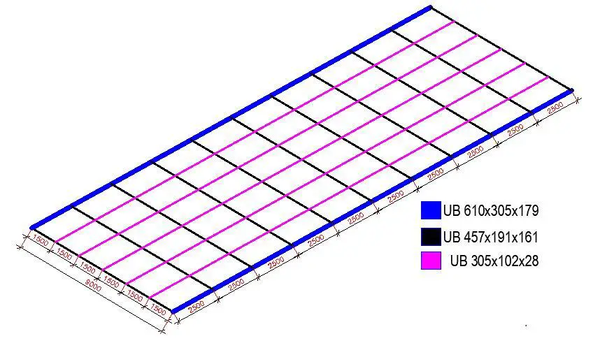
The deck of the bridge is composed of primary and secondary steel beam members. The floor beams consist of UB 457x191x161 members supported by the UB 610x305x179 bottom chord rail of the trusses and spaced at 2.5m intervals. The stringers are the secondary UB 305x102x28 members running parallel to the bottom chord and spaced at 1.5m. A 200mm thick reinforced concrete deck is expected to sit on the beams.
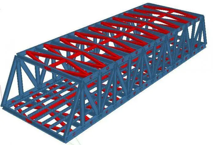
The truss bridge has been modelled on Staad Pro software as shown below. The top of the truss bridge (top chord) will be braced using UB 254x146x37 members in a K-truss arrangement (see below) to restrain the top chord from sway under wind action.

Loading
In this article, the truss bridge will be analysed for the self-weight (all
dead and superimposed loads) and traffic load. All other environmental loads and indirect actions will not be considered.
Dead Load
(1) Self-weight of steel members (to be calculated automatically by Staad Pro)
(2) Self-weight of 200mm thick reinforced concrete deck = 0.2 × 25 = 5 kN/m2
(3) Self-weight of 75mm thick asphalt wearing course = 0.075 × 23.5 = 1.8 kN/m2
Total pressure dead load = 6.8 kN/m2
Live Load
According to the requirements of Load Model 1 (LM 1), the carriageway width of 9m can be divided into three notional lanes as shown below;
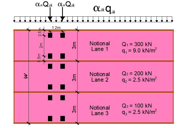
In essence, the traffic on the bridge will be represented by the UDL as specified above and the tandem system. The worst effect of the wheel load on the bridge deck will be considered. However, it is important that the influence line analysis of the bridge be carried out, in order to determine the wheel load location that will produce the worst effects on the structure.

Bottom Chord Analysis Results
The result below depicts the internal stresses induced in the bottom chord at the load combination 1.35gk + 1.5qk (where qk represents the UDL component of the traffic load only).

The result below depicts the internal stresses induced on the bottom chord under the unfactored moving tandem wheel load only.

A little consideration will show that the following results are applicable for the bottom chord;
Design Axial compression (member 1): 462.892 + 1.5(300.842) = 914.155 kN
Design axial tension (members 5 and 6) = 457.486 + 1.5(321.591) = 939.8725 kN
Design major bending moment (member 3): 231.737 + 1.5(231.617) = 579.1625 kNm
Design minor axis bending moment = 2.541 + 1.5(1.590) = 4.926 kNm
Design Shear (major axis) = 101.619 + 1.5(158.288) = 339.051 kN
Design Shear (minor axis) = 1.853 + 1.5(1.17) = 3.609 kN
It is obvious that these maximum forces do not interact on the same point in the section. However, for the sake of simplicity, let us assume they interact at the same point in the structure. The design verifications are as follows;
Design of the Bottom Chord
| Section s1 results summary | Unit | Capacity | Maximum | Utilisation | Result |
| Shear resistance (y-y) | kN | 1441.9 | 339.1 | 0.235 | PASS |
| Shear resistance (z-z) | kN | 2047.7 | 3.6 | 0.002 | PASS |
| Bending resistance (y-y) | kNm | 1470.0 | 579.2 | 0.394 | PASS |
| Bending resistance (z-z) | kNm | 303.1 | 4.9 | 0.016 | PASS |
| Compression resistance | kN | 5598.0 | 914.2 | 0.163 | PASS |
| Comb. bending and axial force | 0.571 | PASS |
Section details
Section type; UB 610x305x179 (BS4-1)
Steel grade – EN 10025-2:2004; S275
Nominal thickness of element; tnom = max(tf, tw) = 23.6 mm
Nominal yield strength; fy = 265 N/mm2
Nominal ultimate tensile strength; fu = 410 N/mm2
Modulus of elasticity; E = 210000 N/mm2
Classification of cross sections – Section 5.5
ε = √[235 N/mm2 / fy] = 0.94
Internal compression parts subject to bending and compression – Table 5.2 (sheet 1 of 3)
Width of section; c = d = 540 mm
α = min([h / 2 + NEd / (2 × tw × fy) – (tf + r)] / c, 1) = 0.727
c / tw = 38.3 = 40.7ε ≤ 396ε / (13α – 1); Class 1
Outstand flanges – Table 5.2 (sheet 2 of 3)
Width of section; c = (b – tw – 2r) / 2 = 130 mm
c / tf = 5.5 = 5.8ε ≤ 9ε; Class 1
Section is class 1
Check compression – Section 6.2.4
Design compression force; NEd = 914.2 kN
Design resistance of section – eq 6.10;
Nc,Rd = Npl,Rd = Afy / γM0 = 6044.2 kN
NEd / Nc,Rd = 0.151
PASS – Design compression resistance exceeds design compression
Slenderness ratio for y-y axis flexural buckling – Section 6.3.1.3
Critical buckling length; Lcr,y = Ly_s1 = 2500 mm
Critical buckling force; Ncr,y = π2EIy / Lcr,y2 = 507456.5 kN
Slenderness ratio for buckling – eq 6.50; λy = √(Afy / Ncr,y) = 0.109
Check y-y axis flexural buckling resistance – Section 6.3.1.1
Buckling curve – Table 6.2; a
Imperfection factor – Table 6.1;αy = 0.21
Buckling reduction determination factor; φy = 0.5[1 + αy(λy – 0.2) + λy2] = 0.496
Buckling reduction factor – eq 6.49; χy = min[1 / (φy + √(φy2 – λy2)), 1] = 1
Design buckling resistance – eq 6.47;
Nb,y,Rd = χyAfy / γM1 = 6044.2 kN
NEd / Nb,y,Rd = 0.151
PASS – Design buckling resistance exceeds design compression
Slenderness ratio for z-z axis flexural buckling – Section 6.3.1.3
Critical buckling length; Lcr,z = Lz_s1 = 2500 mm
Critical buckling force; Ncr,z = π2EIz / Lcr,z2 = 37832.1 kN
Slenderness ratio for buckling – eq 6.50; λz = √(Afy / Ncr,z) = 0.4
Check z-z axis flexural buckling resistance – Section 6.3.1.1
Buckling curve – Table 6.2; b
Imperfection factor – Table 6.1; αz = 0.34
Buckling reduction determination factor;
φz = 0.5(1 + αz(λz – 0.2) + λz2) = 0.614
Buckling reduction factor – eq 6.49;
χz = min(1 / (φz + √(φz2 – λz2)), 1) = 0.926
Design buckling resistance – eq 6.47;
Nb,z,Rd = χzAfy / γM1 = 5598 kN
NEd / Nb,z,Rd = 0.163
PASS – Design buckling resistance exceeds design compression
Check of torsional and torsional-flexural buckling showed that the section is okay. – Section 6.3.1.4
Check for shear – Section 6.2.6
Height of web; hw = h – 2tf = 573 mm;
η = 1.000
hw / tw = 40.6 = 43.2ε/η < 72ε/η
Shear buckling resistance can be ignored
Design shear force;
Vy,Ed = 339.1 kN
Shear area – cl 6.2.6(3);
Av = max(A – 2btf + (tw + 2r)tf, ηhwtw) = 9425 mm2
Design shear resistance – cl 6.2.6(2);
Vc,y,Rd = Vpl,y,Rd = Av(fy /√3) / γM0 = 1441.9 kN
Vy,Ed / Vc,y,Rd = 0.235
PASS – Design shear resistance exceeds design shear force
Check bending moment – Section 6.2.5
Design bending moment; My,Ed = 579.2 kNm
Design bending resistance moment – eq 6.13;
Mc,y,Rd = Mpl,y,Rd = Wpl.yfy / γM0 = 1470 kNm
My,Ed / Mc,y,Rd = 0.394
PASS – Design bending resistance moment exceeds design bending moment
Check bending and axial force – Section 6.2.9
Bending and axial force check – eq.6.33 & eq.6.34;
Ny,lim = min(0.25Npl,Rd, 0.5hwtwfy / γM0) = 1070.5 kN
NEd / Ny,lim = 0.854
Allowance need not be made for the effect of the axial force on the plastic resistance moment about the y-y axis
Bending and axial force check – eq.6.35;
Nz,lim = hwtwfy / γM0 = 2141.0 kN
NEd / Nz,lim = 0.427
Allowance need not be made for the effect of the axial force on the plastic resistance moment about the z-z axis
αN = 2
βN = max(5n, 1) = 1
For bi-axial bending – eq.6.41;
[My,Ed / Mpl,y,Rd]αN + [Mz,Ed / Mpl,z,Rd]βN = 0.171
PASS – Biaxial bending utilisation is acceptable
Check combined bending and compression – Section 6.3.3
Equivalent uniform moment factors – Table B.3;
Cmy = 1.000
Cmz = 1.000
CmLT = 1.000
Interaction factors kij for members susceptible to torsional deformations – Table B.2
Characteristic moment resistance;
My,Rk = Wpl.yfy = 1470 kNm
Characteristic moment resistance;
Mz,Rk = Wpl.zfy = 303.1 kNm
Characteristic resistance to normal force;
NRk = Afy = 6044.2 kN
Interaction factors;
kyy = Cmy(1 + min(λy – 0.2, 0.8) × NEd / (χyNRk / γM1)) = 0.986
kzy = min(0.6 + λz, 1 – 0.1λzNEd / ((CmLT – 0.25) × χzNRk / γM1)) = 0.991
kzz = Cmz(1 + min(2λz – 0.6, 1.4) × NEd / (χzNRk / γM1)) = 1.033
kyz = 0.6kzz = 0.620
Interaction formulae – eq 6.61 & eq 6.62;
NEd / (χyNRk / γM1) + kyyMy,Ed / (cLTMy,Rk / γM1) + kyzMz,Ed / (Mz,Rk / γM1) = 0.55
NEd / (χzNRk / γM1) + kzyMy,Ed / (cLTMy,Rk / γM1) + kzzMz,Ed / (Mz,Rk / γM1) = 0.571
PASS – Combined bending and compression checks are satisfied.
Design of the Web Members (Verticals and Diagonals)
The result below depicts the internal stresses induced in the bottom chord at the load combination 1.35gk + 1.5qk (where qk represents the UDL component of the traffic load only).

The result below depicts the internal stresses induced on the bottom chord under the unfactored moving tandem wheel load only.

Design Axial compression : 1181.948 + 1.5(761.358) = 2324 kN
Design axial tension = 928.940 + 1.5(623.655) = 1864 kN
Design major bending moment: (ignored for brevity)
Design minor axis bending moment = (ignored for brevity)
Design Shear (major axis) = (ignored for brevity)
Design Shear (minor axis) = (ignored for brevity)
Classification of cross sections – Section 5.5
ε = √[235 N/mm2 / fy] = 0.92
Internal compression parts subject to compression – Table 5.2 (sheet 1 of 3)
Width of section;
c = b – 3t = 212.5 mm
c / t = 17 = 18.4ε <= 33ε; Class 1
Internal compression parts subject to compression – Table 5.2 (sheet 1 of 3)
Width of section;
c = h – 3t = 212.5 mm
c / t = 17 = 18.4ε <= 33ε; Class 1
Section is class 1
Check compression – Section 6.2.4
Design compression force; NEd = 2324 kN
Design resistance of section – eq 6.10;
Nc,Rd = Npl,Rd = Afy / γM0 = 3219.5 kN
NEd / Nc,Rd = 0.722
PASS – Design compression resistance exceeds design compression
Slenderness ratio for y-y axis flexural buckling – Section 6.3.1.3
Critical buckling length; Lcr,y = Ly_s1 = 5590 mm (considering the length of the diagonal web members)
Critical buckling force;
Ncr,y = π2EIy / Lcr,y2 = 7239.9 kN
Slenderness ratio for buckling – eq 6.50;
λy = √(Afy / Ncr,y) = 0.667
Check y-y axis flexural buckling resistance – Section 6.3.1.1
Buckling curve – Table 6.2; a
Imperfection factor – Table 6.1; ay = 0.21
Buckling reduction determination factor;
φy = 0.5[1 + αy(λy – 0.2) + λy2] = 0.771
Buckling reduction factor – eq 6.49;
χy = min[1 / (φy + √(φy2 – λy2)), 1]= 0.863
Design buckling resistance – eq 6.47;
Nb,y,Rd = χyAfy / γM1 = 2777.7 kN
NEd / Nb,y,Rd = 0.837
PASS – Design buckling resistance exceeds design compression
For completeness, the section should be checked for shear, torsional buckling, and axial/moment interaction.
Conclusion
The method adopted in this article is suitable for draft/preliminary designs. The approach can be extended and used to design and select all the members of the truss bridge. For instance, a little review of the design of the bottom chord shows that there is still room for reduction of the member size, while the same cannot be said for the web members.
The floor beams of the section will need to be designed as a composite beam, taking into account the interaction of the concrete deck. After all the members have been selected and checked, a detailed/final analysis and design can be carried out, to verify the suitability of the selected members.







it’s a interesting send me more
You are multiplying the load effect by the load combination factors. I believe that you should apply the load combination to the loading rather than the load effects.