Trusses deflect when loaded. Under gravity loads, this is usually characterised by the sagging of the top and bottom chords, and the consequent movement of the web and diagonal members. In the design of trussed structures such as roofs and bridges, it is always important to keep the deflection of the trusses to a minimum in order to maintain the appearance and functionality of the structure. Deflection of trusses can be assessed manually using the virtual work method (unit load method), direct stiffness method, or finite element analysis.
The deflection of roof trusses is often limited to span/240. On the other hand, a span to depth ratio of 15 is often found adequate for all practical purposes. For bridges, AASHTO design code states that the maximum deflection of a truss bridge due to live load should not exceed span/800. The principle of virtual work can be used to compute the maximum deflection of the truss, which is then compared to the allowable deflection.
In this article, we are going to explore how to determine the deflection of trusses using the virtual work method (unit load method). In the virtual work method, the truss is analysed for the axial forces due to the externally applied load. Subsequently, the external forces are removed and replaced with a unit virtual load at the node where the deflection is to be obtained. The direction of the unit load should be in the same direction with where the deflection is sought. The truss is re-analysed for the axial forces in the members due to the virtual unit load.
The summation of the deflection of the individual members using the formula below gives the deflection of the roof truss at the point of interest.
δ = ∑niNiLi/EiAi
Where;
n = axial force in member i due to virtual unit load
N = axial load in member i due to externally applied load
L = length of member
E = Modulus of elasticity of member
A = Area of member
Worked Example
A truss is loaded as shown below. Obtain the vertical deflection at point C due to the externally applied load (AE = constant).
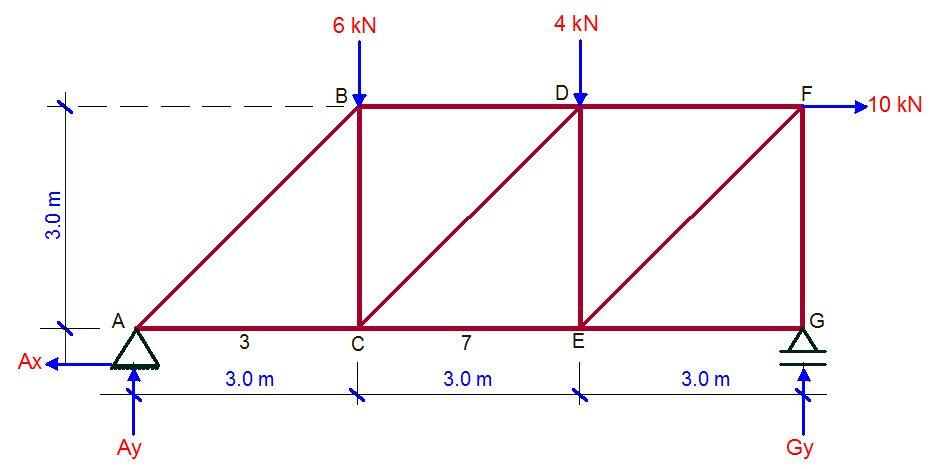
Support Reaction due to externally applied load
Let ∑MG = 0;
9Ay – (6 × 6) – (4 × 3) + (10 × 3) = 0
Ay = 2 kN↑
Let ∑MA = 0;
9Gy – (10 × 3) – (4 × 6) – (6 × 3) = 0
Gy = 8 kN ↑
Let ∑Fx = 0
Ax = 10 kN ←
Internal forces due to the externally applied loads
Joint A
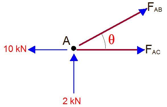
∑Fy = 0
2 + FABsin45 = 0
FAB = -2.8 kN (compression)
∑Fx = 0
-10 + FAC + FABcos45 = 0
-10 + FAC – 2.8cos45 = 0
FAC = 12 kN (tension)
Joint B
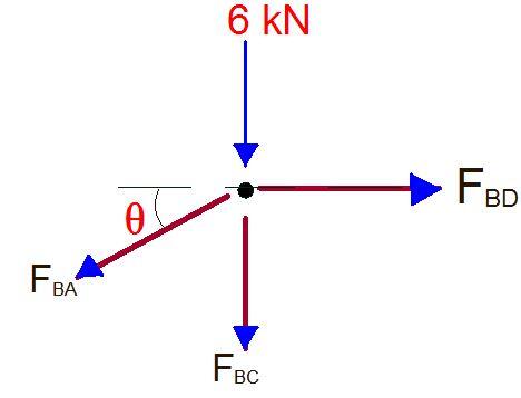
∑Fx = 0
FBD – FBAcos45 = 0
FBD – 2.8cos45 = 0
FBD = -2 kN (compression)
∑Fy = 0
-6 – FBC – FBAsin45 = 0
-6 – FBC + 2.8sin45 = 0
FBC = -4 kN (tension)
JOINT C
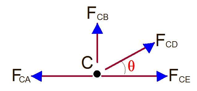
∑Fy = 0
FBC + FCDsin45 = 0
-4 + FCDcos45 = 0
FCD = 5.656 kN (tension)
∑Fx = 0
-FCA + FCDcos45 + FCE = 0
-12 + 5.656cos45 + FCE = 0
FCE = 8 kN (tension)
JOINT G
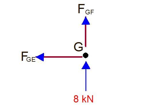
∑Fy = 0
8 + FGF = 0
FGF = -8 kN (compression)
∑Fx = 0
FGE = 0
JOINT F
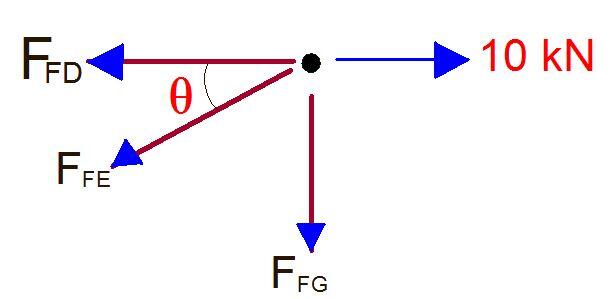
∑Fy = 0
-FFG – FFEsin45 = 0
-(-8) – FFEsin45 = 0
FFE = 11.31 kN (tension)
∑Fx = 0
-FFD – FFEcos45 + 10 = 0
-FFD – 11.31cos45 + 10 = 0
FFD = 2 kN (tension)
JOINT E
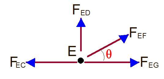
∑Fy = 0
FED + FEFsin45 = 0
FED + 11.31sin45 = 0
FED = -8 kN (compression)
Having obtained the internal forces in all the members due to the externally applied loads, let us remove all the loads and replace them with a unit vertical load at point C as shown below;
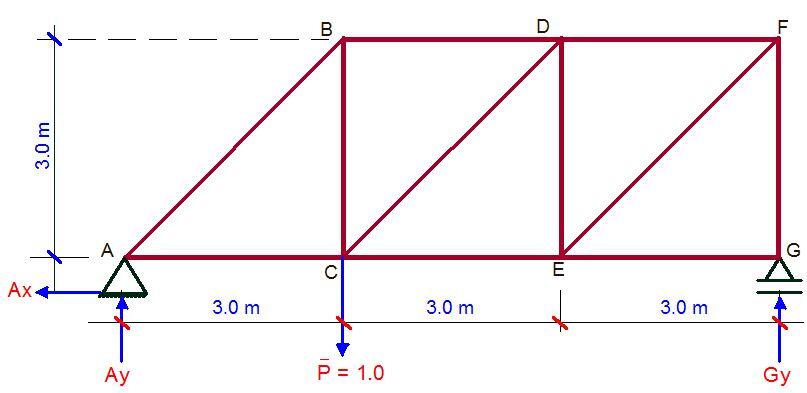
Support Reaction due to virtual load
Let ∑MG = 0;
9Ay – (1 × 6) = 0
Ay = 6/9 = 0.667 ↑
Let ∑MA = 0;
9Gy – (1 × 3) = 0
Gy = 3/9 = 0.333 ↑
Let ∑Fx = 0
Ax = 0
When analysed using the same procedure as above;
FAC = 0.665 (tension)
FAB = -0.941 (compression)
FBC = 0.665 (tension)
FCE = 0.334 (tension)
FCD = 0.47 (tension)
FBD = 0.665 (compression)
FDE = 0.331 (compression)
FDF = 0.333 (compression)
FEF = 0.47 (tension)
FEG = 0
FGF = 0.333 (compression)
We can now form a table as follows;
| Member | n | N (kN) | L (m) | nNL/AE |
| AC | +0.665 | +12.00 | 3.000 | 23.940 |
| AB | -0.940 | -2.80 | 4.243 | 11.167 |
| BC | +0.665 | -4.00 | 3.000 | -7.980 |
| CE | +0.334 | +8.00 | 3.000 | 8.016 |
| CD | +0.470 | +5.65 | 4.243 | 11.267 |
| BD | -0.665 | -2.00 | 3.000 | 3.990 |
| DE | -0.331 | -8.00 | 3.000 | 7.944 |
| DF | -0.331 | +2.00 | 3.000 | -1.986 |
| EF | +0.470 | +11.31 | 4.243 | 22.554 |
| EG | 0 | 0 | 3.000 | 0.000 |
| GF | -0.333 | -8.00 | 3.000 | 7.992 |
| ∑niNiL = 86.904/AE |
Therefore the vertical deflection at point C is 86.904/AE metres.

