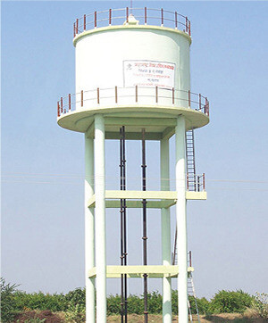
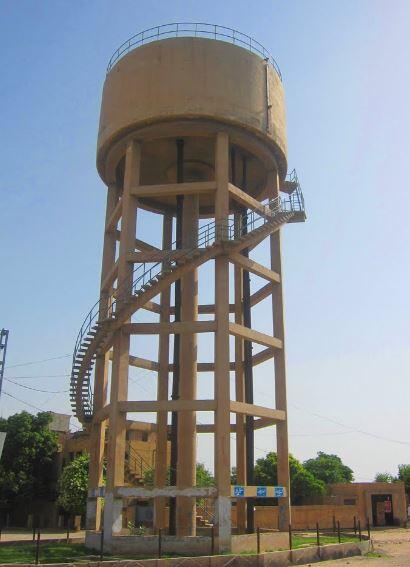
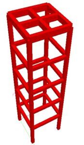
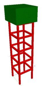
Reinforced concrete overhead tanks are water retaining structures that are placed at a height above the natural ground level. The major reason for placing the tanks at a height is to enable the water to flow under gravity to the point where they are needed. Since the tank is to be supported at a height, there is a need for a tank stand/support system, which is usually constructed of reinforced concrete, and cast monolithically with the tank shell.
The design of reinforced concrete overhead tank involves the determination of the dimensions of the tank shell to hold the desired volume of water, selection of an adequate concrete section and steel reinforcements to satisfy ultimate and serviceability limit state requirements of the tank shells, and selection of adequate column and beam sizes with the proper reinforcements to serve as the support system (tank stand).
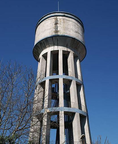
The design of overhead tanks follows the same basic principles as other reinforced concrete structures, with the exception of the special attention paid to the crack width of the tank shell in order to ensure the water-tightness of the structure. In principle, the elements usually designed for in reinforced concrete overhead tanks are;
- The tank shell
- The beams
- The columns
- Other bracing systems (if any),
- Other ancillary components like stairs and rails, and
- The foundation
Design of the Tank Shell
The shell of the tank is the major water-holding element of the structure, which usually comprises the walls, the base, and the cover. The volume of the tank shell can be estimated by considering the water demand of the end-users of the tank, and the anticipated frequency of pumping. Furthermore, space constraints and construction challenges can also influence the final volume and shape of the tank. Typically, it is more common to calculate the volume of the tank, and then select the desired height and plan area.
The cross-section of the tank can be rectangular or circular. Circular tanks usually give more economical sections and reinforcements than rectangular tanks, even though they are more difficult to construct. Other shapes can be designed for as long the engineer can guarantee the construction feasibility and economical implication of such decisions.
Since the tank shells are liquid containment elements, the walls and base are subjected to hydrostatic pressure from the stored water. The walls are also subjected to direct tension (for rectangular walls), and hoop tension (for circular walls). Therefore, the tank shell should have an adequate cross-section that will be able to withstand the pressure from the stored water. The design pressure is normally used to obtain the design moment, which can be used to provide the thickness of the sections and the reinforcements. The restraint condition of the tank walls influences the moment distribution (or the nature of the bending moment diagrams) which can ultimately influence the final arrangement of reinforcements.

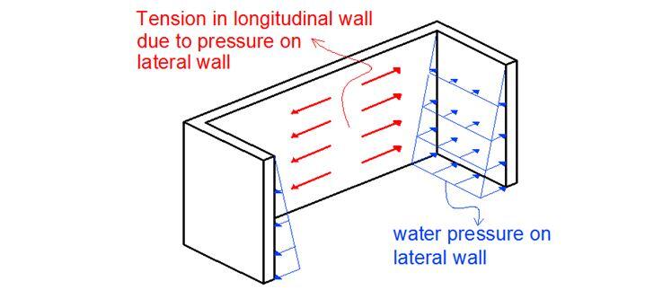
In order to guarantee the water-tightness of the tank shell from a structural point of view, the crack width of the tank shell should not exceed 0.2 mm. This encompasses long and short-term cracking from flexure, shrinkage, and restraints within the concrete system. However, experience has shown that this serviceability limit state requirement usually governs the design of water retaining structures since the reinforcement required to achieve the minimum crack width is usually greater than that required to control flexure and shear.
Design of the Beams in Reinforced Concrete Overhead Tanks
Depending on the structural scheme adopted, the load from the weight of the tank and the stored water may be transferred to the supporting beams before being transferred to the columns (see Figure 4). In some cases, a flat slab concept may be adopted where the base of the tank is supported directly by columns as shown in Figure 5.
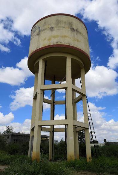
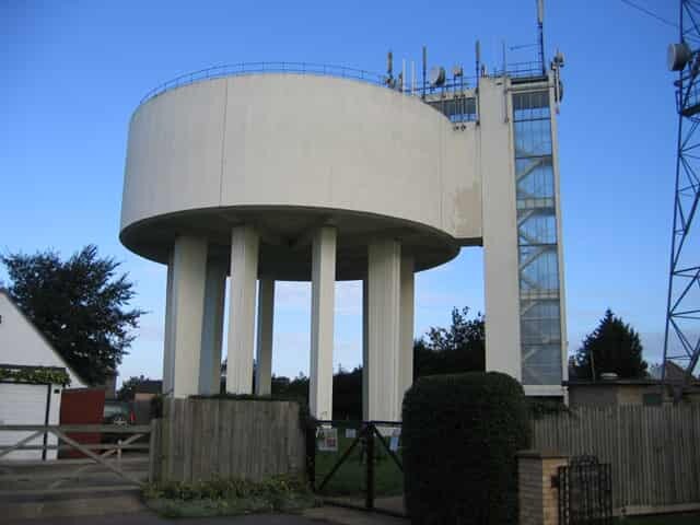
However, the design concept of the beams is similar to the design concept of normal reinforced concrete beams. For the design of circular beams, it will be important to consider the effects of torsion. The procedure for the design of circular beams is readily available in literature.
Design of the columns
The design of the supporting columns in an reinforced concrete overhead tank is similar to the design of normal reinforced concrete columns. The columns will be subjected to axial force, bending, and shear from the self weight of the materials, the stored water, and wind. The size and arrangement of the columns will depend on the anticipated load from the water tank.
Furthermore, special attention must be paid to the to the concrete cover to the reinforcements in order to guarantee the durability of the structure. For the design of the columns, it will be very important to consider to consider second-order effects (p-delta) since such structures could be susceptible to such.
Design of the bracing system
More often than not, reinforced concrete overhead tanks are not provided with additional bracing systems apart from the normal beams and columns. In other words, the structure relies on the frame elements for structural stability. As a result of this, the columns should be designed as unbraced columns since they resist the horizontal loads coming to the structure.
Apart from introducing shear walls or cores, introducing diagonal or cross-bracings will likely pose significant construction and aesthetic challenges.
Design of the ancillary components
Ancillary components such as stairs and rails are provided in reinforced concrete overhead tanks for ease of movement and safety up and down the tank. Such features are important for regular inspection and maintenance of the tank after it is constructed. The stair can be made up of steel straight ladders attached to the frame, or constructed as a regular flight staircase to the top. The decision on the type of staircase will depend on the size and complexity of the water tank.
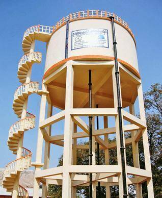
For circular water tanks, a spiral or helical staircase can be provided to wrap around the columns as shown in Figure 6.
The stairs should be firm, durable, and be able to carry the anticipated design live load. Furthermore, the rails should be able to resist direct human actions such as pulling, leaning, and mild impacts.
Design of the Foundation
The type of foundation adopted for a reinforced concrete overhead tank should depend on the height of the tank, the anticipated load, and the type of soil. On very weak and marginal soils, deep foundations such as piles may be required to send to the superstructure load to a firmer stratum.
Furthermore, for lightly loaded water tanks on a firm soil, isolated pad foundations may be provided. However, it will be in the best of the structure to ‘chain’ the entire columns together such that the foundation will behave as one unit. This will guide against the detrimental effects of differential settlement which might compromise the integrity of the superstructure. It is important to guide against secondary/indirect stresses that may cause cracks in the tank shell.
Design Example
It is desired to provide a reinforced concrete overhead water tank (not to exceed 15m high) to serve an estate of 50 households. Design the structure using relevant design standards and by making reasonable assumptions. There are no space constraints. Allowable bearing capacity of the soil = 100 kN/m2
Solution
Let us assume that each household has an average of 5 persons with a water demand of 120 litres per capita per day.
Volume of water required per day = 50 × 5 × 120 = 30000 litres = 30 m3
Making allowance for other miscellaneous uses such as the washing of cars, emergency fire fighting, etc, let us increase the volume to 35 m3.
Let the height of the tank shell (in-to-in) be 2.5 m.
Therefore the plan area of the tank = 35/2.5 = 14 m2
Let us adopt a square tank of dimensions 3.75 m × 3.75 m (Area provided = 14.06 m2)
Total volume of water anticipated (L x B x H) = 3.75 m × 3.75m × 2.5m = 35.16 m3
Initial Dimensions
Thickness of the tank shells =250 mm
Dimension of the tank shell supporting beams = 450 x 250 mm
Dimension of the bracing beams = 250 x 250 mm
Dimension of the columns = 250 x 250 mm
Therefore the centre-to-centre spacing of the square tank shell will be 4 m (such that the in-to-in dimensions will be 3.75 m).
Total weight of water = 10 kN/m3 × 35.16 m3 = 351.6 kN
The load combinations considered in the design of the reinforced concrete overhead tank are;
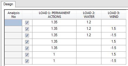
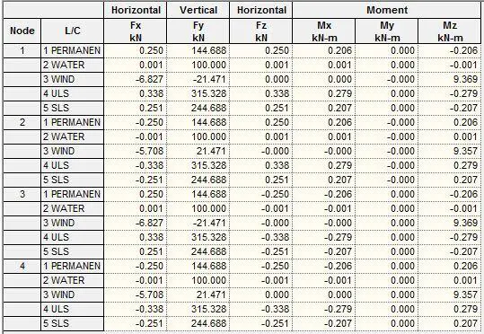
When analysed on Staad Pro, the support reactions obtained were as shown below. The maximum column axial force obtained at ultimate limit state was 315.328 kN, while the maximum service load was 244.688 kN. Therefore, with a soil bearing capacity of 100 kN/m2, a square pad footing of 1650 mm x 1650 mm should be adequate. A plinth beam beam can be introduced to chain the separate bases together.
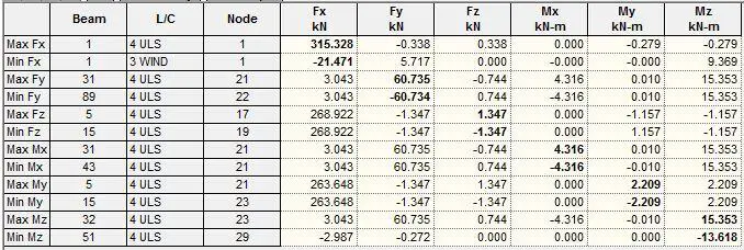
The summary of the maximum internal stresses obtained from the analysis is shown below;
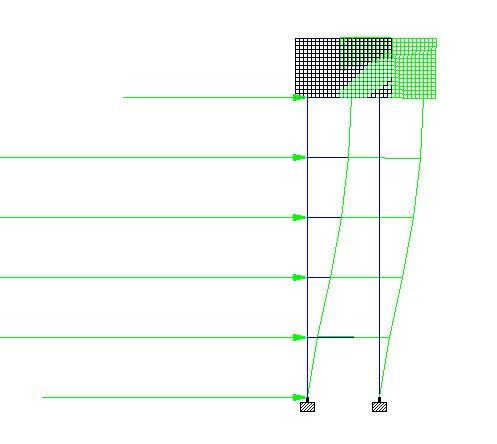
(a) Deflection of the tank stand due to wind load 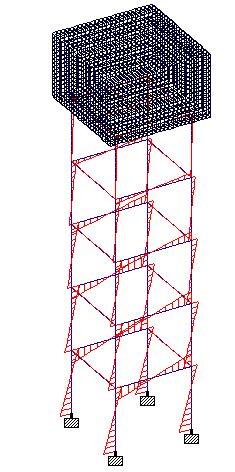
(b) Bending moment of the tank stand due to the effect of wind 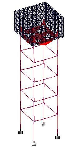
(c) Bending moment on the tank stand due to gravity actions
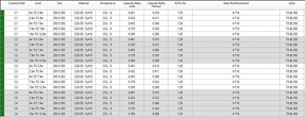
The summary of the column design results is shown below. The results show that 4-T16 as the main bars and T8@250 c/c spacing as links is sufficient for the columns.
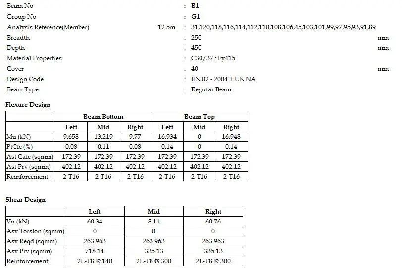
A snippet of one of the beam design results is shown below;
The slab analysis result is shown below;
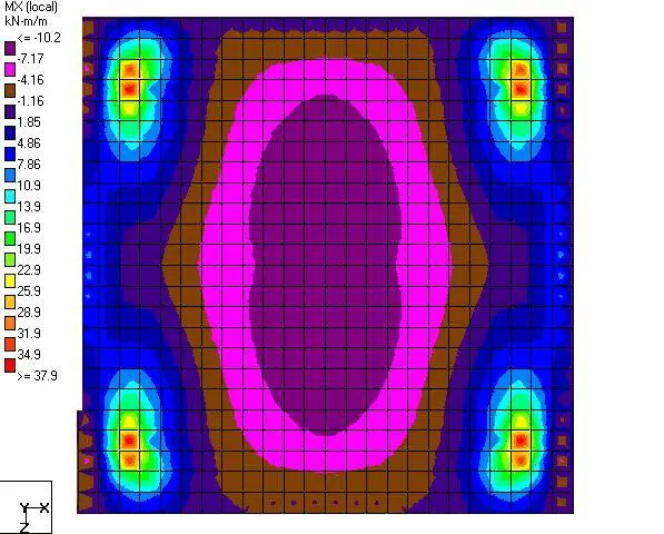
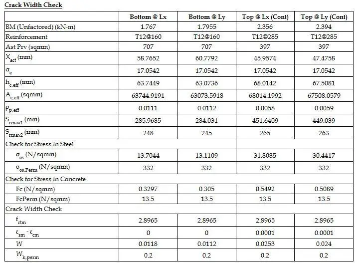
For the bottom slab of the tank shell, T12@160 c/c bottom reinforcements and T12@285 c/c Top reinforcements satisfied flexural and crackwidth requirements. See the snippet below.
