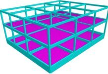
Buckling of thin plates occurs when a plate moves out of plane under compressive load, causing it to bend in two directions. The buckling behaviour of thin plates is significantly different from the buckling behaviour of columns. Buckling in a column terminates the member’s ability to resist axial force, and as a result, the critical load is the member’s failure load. The same cannot be said for the buckling of thin plates due to the membrane action of the plate.
Plates under compression will continue to resist increasing axial force after achieving the critical load, and will not fail until a load far greater than the critical load is attained. As a result, a plate’s elastic critical load is not the same as its failure load. Instead, the load-carrying capability of a plate must be determined by examining its post-buckling behaviour.
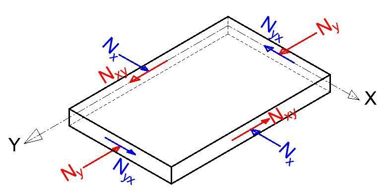
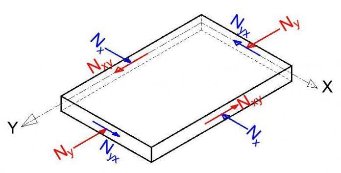
A governing equation in terms of biaxial compressive forces Nx and Ny and constant shear force Nxy, as shown in Figure 1, can be developed to estimate the critical in-plane loading of a plate using the idea of neutral equilibrium.
D[δ4w/δx4 + 2(δ4w)/(δx2δy2) + δ4w)/δy4] + Nx(δ2w/δx2) + Ny(δ2w/δy2) + 2Nxy(δ4w/δxδy) = 0 ——— (1)
All the stress components are expressed in terms of the deflection w of the plate (where w is a function of the two coordinates (x, y) in the plane of the plate). D = Eh3/12(1 – v2) is the flexural rigidity of the plate per unit length; E is the modulus of elasticity; h is the thickness of the plate, and v is Poisson’s ratio.
The critical load for uniaxial compression can be determined from the differential equation:
D[δ4w/δx4 + 2(δ4w)/(δx2δy2) + δ4w)/δy4] + Nx(δ2w/δx2) = 0 ——— (2)
which is obtained by setting Ny = Nxy = 0 in equation (1). For example, in the case of a simply supported plate, equation (1) can be solved to give:
Nx = π2a2D/m2 (m2/a2 + n2/b2)2 ——— (3)
Taking n equal to 1 yields the critical value of Nx (i.e. the smallest value). This means that a plate buckles in such a way that there are several half-waves in the compression direction but only one half-wave in the perpendicular direction. As a result, the formula for the compressive force’s critical value becomes:
Nx(crit) = π2D/a2 [m + 1/m(a2/b2)]2 ——— (4)
The Euler load for a strip of unit width and length a is represented by the first factor in this expression. The second factor denotes the proportion of greater stability gained by the continuous plate compared with that of an isolated strip. The amount of this factor is determined by the magnitude of the a/b ratio as well as the number m, which indicates how many half-waves the plate buckles into. If a is less than b, the second term in the parenthesis of equation (4) is always less than the first, and the expression’s minimum value is reached by assuming m = 1, i.e. that the plate buckles in one half-wave. Nx critical value can be written as follows:
Ncr = kπ2D/b2 ——— (5)
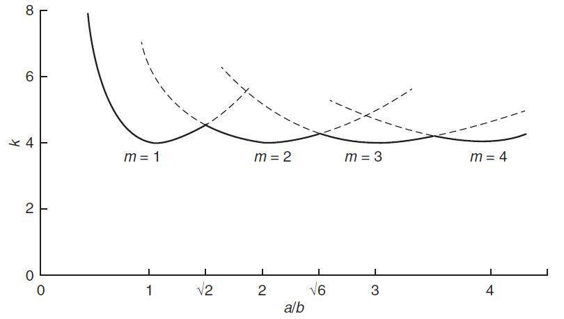
The factor k depends on the aspect ratio a/b of the plate and m, the number of half-waves into which the plate buckles in the x-direction. The variation of k with a/b for different values of m can be plotted as shown in Figure 2. The critical value of Nx is the smallest value that is obtained for m = 1 and the corresponding value of k is equal to 4.0. This formula is analogous to Euler’s formula for buckling of a column.
In the more general case in which normal forces Nx and Ny and the shearing forces Nxy are acting on the boundary of the plate, the same general method can be used. The critical stress for the case of a uniaxially compressed simply supported plate can be written as:
σ = 4π2E/[12(1 – v2)] × (h/b)2 ——— (6)
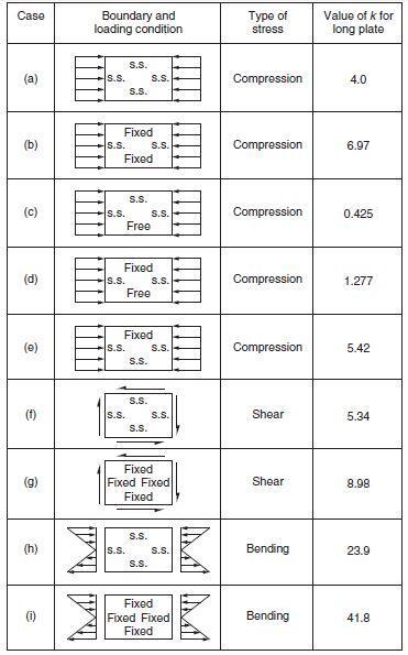
The critical stress values for different loading and support conditions can be expressed in the form:
fcr = kπ2E/[12(1 – v2)] × (h/b)2 ——— (8)
in which fcr is the critical value of different loading cases. Values of k for plates with different boundary and loading conditions are given in Figure 3.
Buckling of Thin Plates in Staad Pro
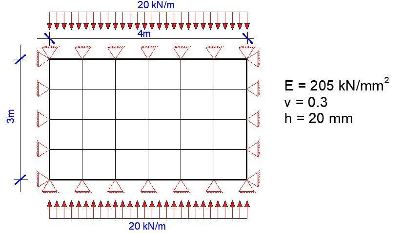
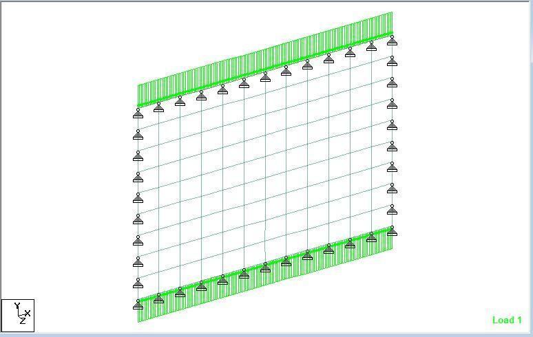
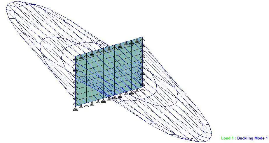
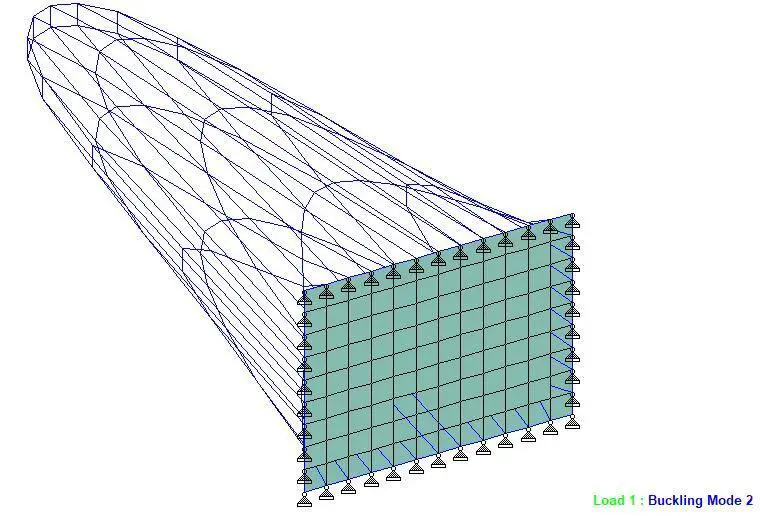
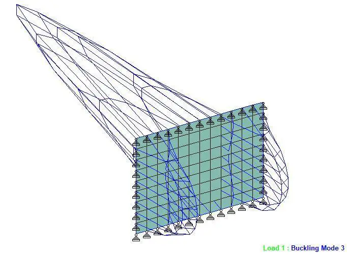
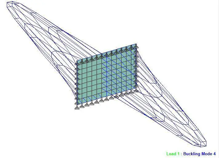
           CALCULATED BUCKLING FACTORS FOR LOAD CASE       1

   MODE               BUCKLING FACTOR

     1                   2957.15142
     2                   3056.42462
     3                  -3102.59328
     4                  -3107.05926
References
Shanmugam N. E. and Narayanan R. (2008): Structural Analysis. In ICE Manual of Bridge Engineering. doi: 10.1680/mobe.34525.0049

