A box girder is formed when two web plates are joined by a common flange at both the top and the bottom. The closed cell which is formed has a much greater torsional stiffness and strength than an open section and this is the main reason why box girder configuration is usually adopted in long span bridges. The torsion and distortion rigidity of box beam is due to the closed section of the box beam.
It has been shown by reseachers that long span bridges with wider decks and eccentric loading on cross-section will suffer in curvature in longitudinal and transverse direction, thereby causing heavy distortion of cross-section. As a result, long span bridges with wide decks should have high torsional rigidity in order to reduce the distortion of cross-section deck to a minimum. This is one of the downsides of T-beam and deck system. Accordingly, box girders are more suitable for larger spans and wider decks, and any eccentric load that will cause high torsional stresses which will be counteracted by the box section (see Figure 1 for typical box girder bridge). However, despite being an efficient cross-section, we should know that that the analysis of such sections are more complicated due combination of flexure, shear, torsion, and distortion. In this post, we are going to evaluate the potentials of Staad Pro software in the analysis of box girder bridge subjected to Load Model 1 of Eurocode 1 Part 2.

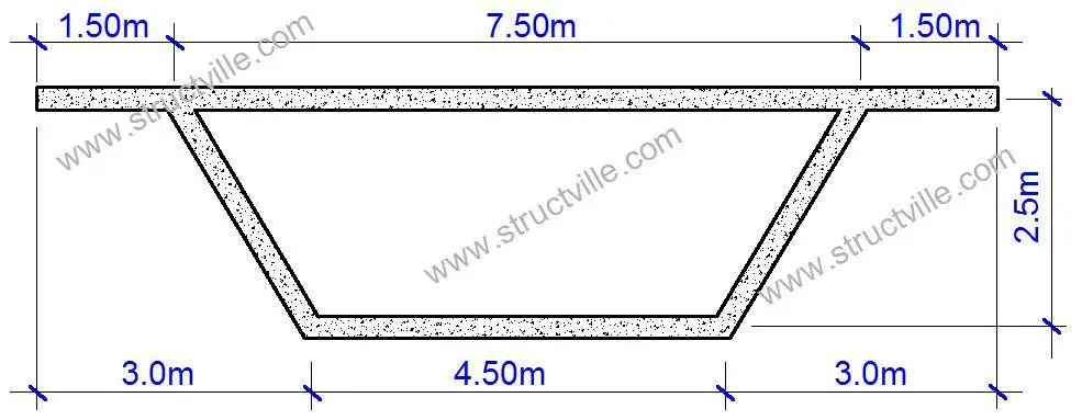
The cross-section of the bridge deck is shown in Figure 2. The following data was used to model the bridge deck on Staad Pro.
Length of bridge = 30 m
Support condition = Pinned to the piers
Unit weight of concrete = 25 kN/m3
Thickness of sections = 250 mm (web and flanges)
Unit weight of asphalt overlay = 22 kN/m3
Thickness of asphalt = 75 mm
Hence, the bridge deck will be subjected to the following actions;
(1) Self weight of girder
(2) Weight of asphalt overlay
(3) Load Model 1 uniformly distributed load
(4) Load Model 1 tandem wheel load (modeled as moving load on Staad Pro)
(5) Pedestrian load on the cantilever
In this analysis, self weight of girder and asphalt were modelled as one load case, Load Model 1 (UDL) and pedestrian action were modeled as a separate load case, while Load Model 1 (tandem wheel load) were modelled as another separate load case.
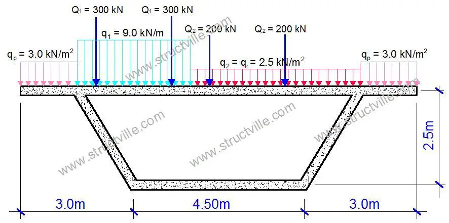
The typical combined traffic action on the bridge deck is shown in Figure 3.
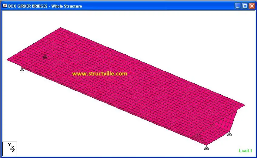
When modelled on Staad Pro, the configuration in Figure 4 was obtained. The rendered 3D view is shown in Figure 5.

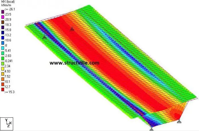
When the structure was analysed, the following results were obtained;
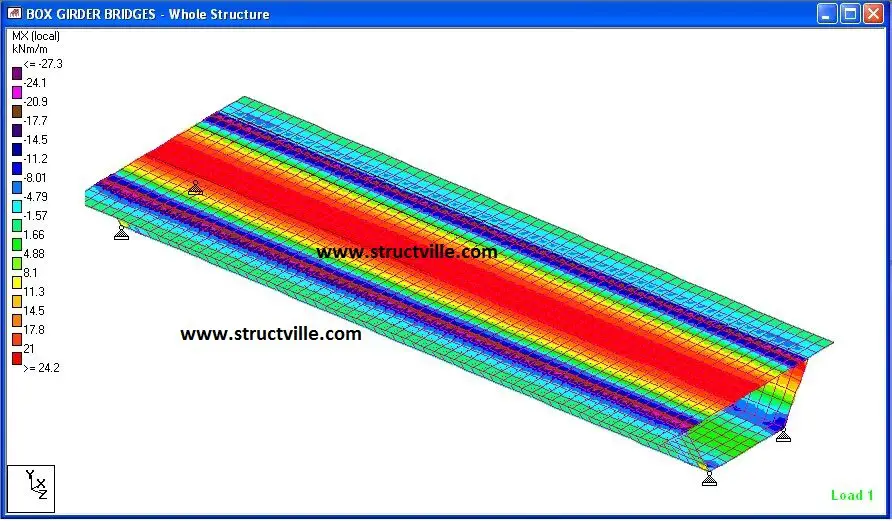
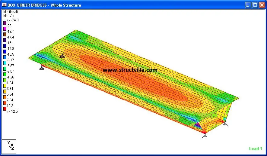
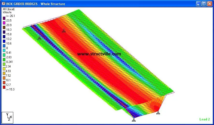
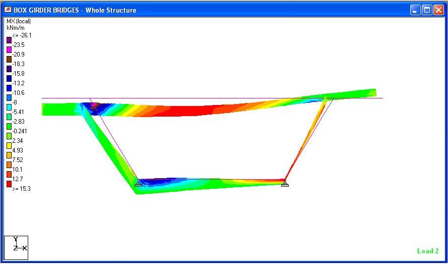
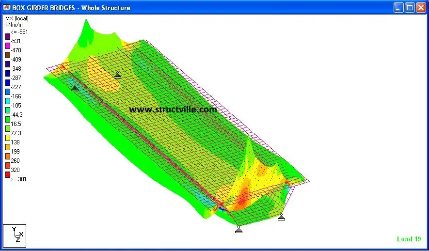
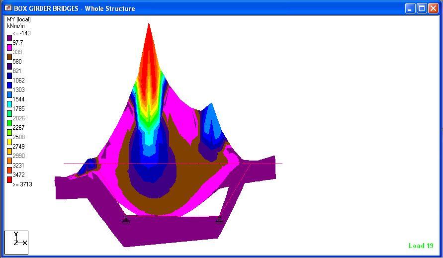
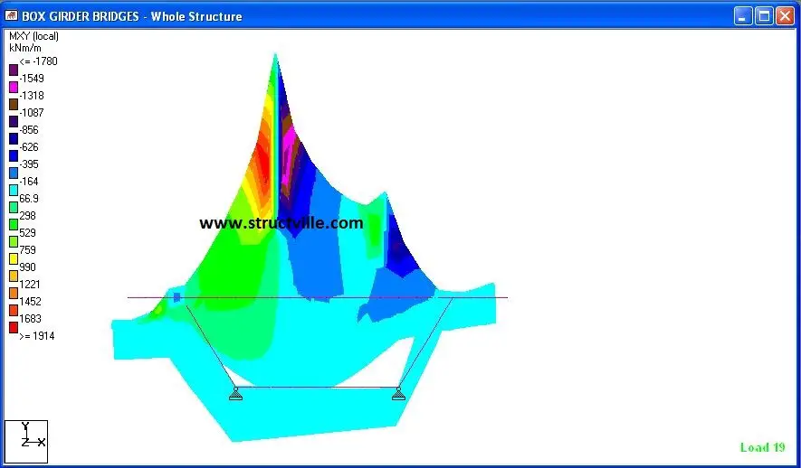
From the results, it could be seen that uniform loads have barely no effect on the torsional-distortional behaviour of box girders, however, unbalanced wheel loads are critical in the behaviour of such structures. We will carry out more studies on this bridge deck behaviour using Staad Pro. Thank you for stopping by today.

