When structural members are subjected to compressive forces, the members may fail before the compressive resistance (A.fy) is reached. This premature failure is usually caused by secondary bending effects such as imperfections, the eccentricity of loading, asymmetry of the cross-section etc. In such cases, the failure mode is normally buckling.
The buckling of columns is usually associated with a sudden large displacement (bending) on the column following a slight increase or modification of an existing compressive load. The load at which the buckling of columns occur is usually less than the compressive resistance of the column, and it is mainly influenced by the length, cross-section, and boundary conditions of the column.
This is unlike when the member is subjected to tensile forces, where the member will generally fail when the stress in the cross-section exceeds the ultimate strength of the material. Members subjected to tensile forces are inherently stable.
In essence, for very short columns or members subjected to tensile forces, the stress is proportional to the load, and the failure load is equal to the yield stress times the area of the cross-section (A.fy). Commonly, compression members can be classified as short, intermediate, or slender depending on their slenderness ratio. Short elements will fail by crushing, slender elements will fail by excessive lateral deflection, and intermediate elements will fail by the combination of both.
Types of Buckling
- Flexural buckling (Euler)
- Lateral-torsional buckling
- Torsional buckling
- Snap-through buckling
- Local plate buckling
In this article, we are going to focus on flexural buckling.
In the year 1757, Leonhard Euler developed a theoretical basis for the analysis of premature failure due to buckling. The theory was based on the differential equation of elastic bending of a pin-ended column, which related the applied bending moment to the curvature along the length of the column.
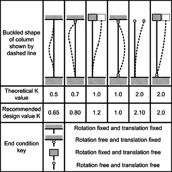
For a pin-ended column, the critical Euler buckling load (K = 1.0) is given by;
PE = Kπ2EI/L2

Note that L in this case is the effective buckling length which depends on the buckling length between the pinned supports or the points of contraflexure for members with other boundary conditions.
Subsequently, the Perry-Robertson formula was developed to take into account the deficiencies of the Euler method. The formula evolved from the assumption that all practical imperfections could be represented by a hypothetical initial curvature of the column. In the UK, the Perry-Robertson formula was modified and is referred to in BS 5950 as the Perry-Strut formula. As a matter of fact, it also forms the basis of flexural buckling in BS EN 1993 (Eurocode 3).
Worked Example on the Buckling of Columns
In the example below, we are going to show how the failure load of a column changes with an increase in effective length due to the phenomenon of buckling.
Let us investigate the load-carrying capacity of UC 305 x 305 x 158 according to EC3. We will consider the ends of the column to be pinned, and we will start with an initial length of 1.0 m.
Properties of UC 305 × 305 × 158
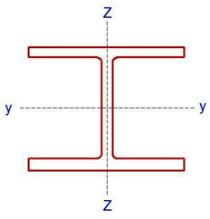
D = 327.1 mm; B = 311.2 mm; tf = 25mm; tw = 15.8mm; r = 15.2mm; d = 246.7mm, b/tf = 6.22; d/tw = 15.6; Izz = 38800 cm4; Iyy = 12600 cm4; iy-y = 13.9cm; iz-z = 7.9 cm, A = 201 cm2
Thickness of flange tf = 25mm.
Since tf > 16mm, Design yield strength fy = 265 N/mm2 (Table 3.1 EC3)
Section classification
ε = √(235/fy ) = √(235/265) = 0.942
We can calculate the outstand of the flange (flange under compression)
C = (b – tw – 2r) / (2 ) = (327.1 – 15.8 -2(15.2)) / (2 ) = 140.45mm.
We can then verify that C/tf = 140.45/25 = 5.618
5.618 < 9ε i.e. 5.618 < 8.478.
Therefore the flange is class 1 plastic
Web (Internal compression)
d/tw = 15.6 < 33ε so that 15.6 < 31.088. Therefore the web is also class 1 plastic
Resistance of the member to uniform compression (clause 6.2.4)
NC,Rd = (A.Fy)/γmo = (201 × 102 × 265) / 1.0 = 5326500 N = 5326.5 kN
Buckling resistance of member (clause 6.3.1)
Since the member is pinned at both ends, the critical buckling length is the same for all axis Lcr = 1000 mm
Slenderness ratio ¯λ = Lcr/(ri λ1)
λ1 = 93.9ε = 93.9 × 0.942 = 88.454
In the major axis
(¯λy ) = 1000/(139 × 88.454) = 0.081
In the minor axis
(¯λz ) = 1000/(79 × 88.454) = 0.143
Check h/b ratio = 327.1/311.2 = 1.0510 < 1.2, and tf < 100 mm (Table 6.2 EN 1993-1-1:2005)
Therefore buckling curve b is appropriate for the y-y axis, and buckling curve c for the z-z axis. The imperfection factor for buckling curve b, α = 0.34 and curve c, α = 0.49 (Table 6.1)
Φ = 0.5 [1 + α(¯λ – 0.2) + ¯λ2]
Φz = 0.5 [1 + 0.49 (0.143 – 0.2) + 0.1432 ] = 0.496
Φy = 0.5 [1 + 0.34 (0.081 – 0.2) + 0.0812 ] = 0.483
X = 1/(Φ + √(Φ2 -¯λ2))
Xz = 1/( 0.496 + √(0.4962 – 0.1432)) = 1.02 > 1 (cannot be greater than 1, so take 1.0)
Xy = 1/( 0.483 + √(0.4832 – 0.0812)) = 1.04 > 1 (cannot be greater than 1, so take 1.0)
Therefore Nb,Rd = (Xz A.Fy)/γm1 = (1.0 × 201 × 102 × 265) / (1.0 ) = 5326500 N = 5326.5 kN
Nb,Rd = NC,Rd = 5326.5 kN
This tells us that the column is short and that at a length of 1.0 m, the column will fail by crushing. Buckling is not a significant mode of failure. If we incrementally increase the length of the column by 1.0 m and follow the steps described above, we will arrive at the following results;
| Column length (m) | Failure Load (kN) |
| 1 | 5326 |
| 2 | 3090 |
| 3 | 4700 |
| 4 | 4270 |
| 5 | 3810 |
| 6 | 3330 |
The graph of the relationship is given below;

Therefore, the load-carrying capacity of compression members reduces with an increase in length. When the height of the pin-ended column was increased from 1m to 6m, a reduction of about 37% was observed in the buckling load. In the design of axially loaded members such as trusses, it is, therefore, advisable to design the members in such a way that the longer members are in tension and the shorter members are in compression.
Thank you for visiting Structville today, and God bless.


• Hmm it looks like your blog ate my first comment (it was super long) so I guess I’ll just sum it up what I wrote and say, I’m thoroughly enjoying your blog. I too am an aspiring blog writer but I’m still new to the whole thing. Do you have any helpful hints for rookie blog writers? I’d definitely appreciate it.
BIM Consulting in USA
BIM documentation in USA
BIM Implementation in USA
Well I have just been reading your website. I sought a lot of deign, structure calculation in frames. One of the idea I was liked is the real design calculation building design.