Piers and abutments are typically employed as support structures for bridge decks. Basically, they transmit the superstructure load of the bridge to the foundation, which is supported on the soil. Piers, abutments, and foundations make up the substructure of any bridge. Therefore, they are influential parameters in the modelling of the foundation of bridges.
The stiffness of the piers, abutments, foundations, and soil all play a role in determining the safety and stability of a bridge. Piers and abutments are subjected to a variety of loading conditions, including live and dead loads from the superstructure; substructure dead load; soil pressure; wind load on the superstructure, substructure, and vehicles; pressure caused by streamflow and ice; and earthquake load.
Furthermore, indirect actions such as support settlement have secondary effects that cause considerable changes in the distribution of internal stresses inside the bridge deck. As a result, it is very important for a bridge designer to pay close attention to the stiffness of substructures when modelling the foundation of bridges. The relative stiffnesses of all of a bridge’s components determine how forces are distributed throughout the superstructure and substructure. The substructure of a bridge is intended to provide stability, strength, and be within the allowable bearing pressure of the soil.
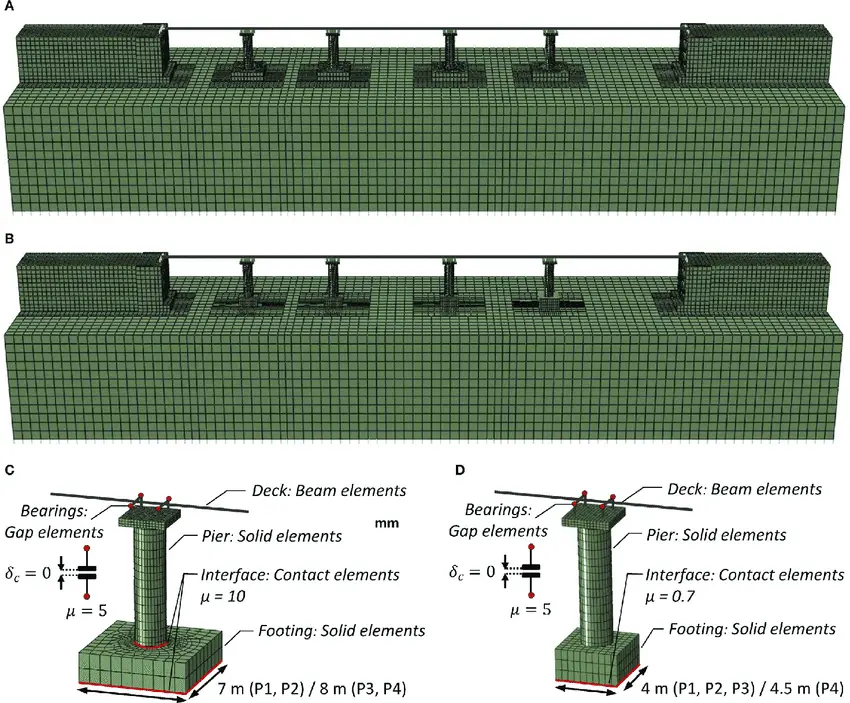
Continuous structures (statically indeterminate structures) can be very efficient at redistributing internal forces, but they are also very susceptible to the effects of differential settlement. The relative stiffnesses of all the components of the bridge, including the individual bearings, have a considerable impact on the distribution of forces throughout the foundation system of the structure. A box girder bridge deck, for example, is particularly sensitive to differential settlement and bearing compression despite its high resistance to torsion and distortion.
In the design of foundation of bridges, any suitable load combination for bridges can be used. One load combination might be the most important for stability, while another might cause the most stress in the concrete or reinforcing steel, and a third might result in the most soil pressure.
Furthermore, if a portion of the pier is submerged underwater, the effect of buoyancy (uplift) must be taken into account when evaluating the pier’s stability. Bridge foundation design can be challenging because of the numerous load combinations that can occur. To assess the stability, earth pressures, and allowable soil bearing pressures, a thorough soil investigation should be carried out. Before choosing a bridge location and type in an earthquake zone, the position of fault zones, slide regions, or any other potentially big unstable ground areas should be thoroughly investigated.
Load Transmission to Foundation of Bridges
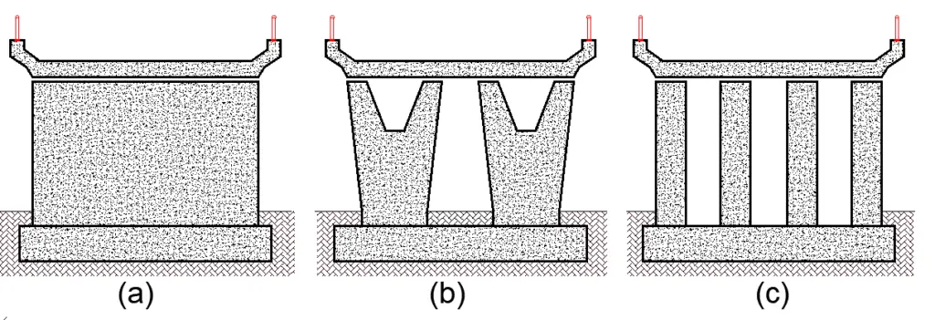
Loads from the superstructure will be transmitted to the foundation by direct compression or compression and bending, depending on the shape of the substructure. The deck loads are transmitted to the foundations by direct compression through the piers depicted in Figure 2(a) to (c).
Structures with a cross-head beam or cantilever, as seen in Figure 3(a) and (b), on the other hand, may have a lot of flexibility (Hambly, 1991).
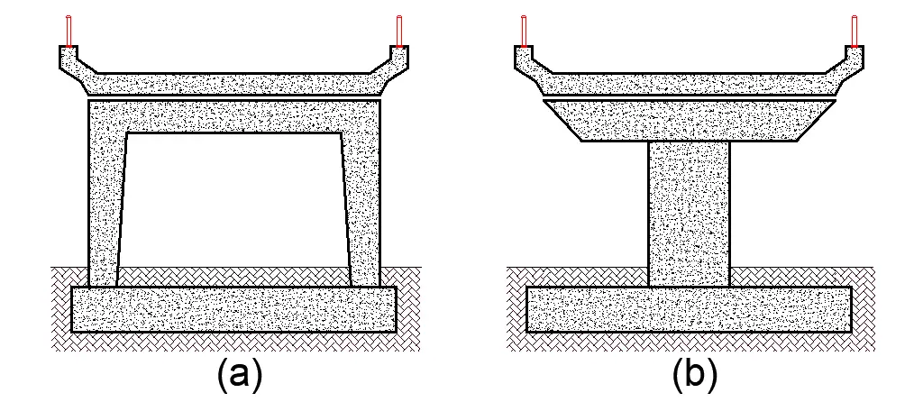
When analysing a bridge deck on such supports using a grillage analysis, it may be essential to represent both the deck and the cross-head. It might be simpler to model the structure using a space frame that mimics the pier’s shape. The foundation stiffnesses and compressible bearings with vertical members between deck and cross-head are then reasonably straightforward to model.
Bridge Foundation Stiffness and Interaction with Soil
When a foundation is subjected to dynamic loading, it will experience a vibration of the same frequency as the applied force. It is therefore critical to set a limit on the amount of dynamic force that the foundations can withstand. There is a certain amount of dynamic motion that can be allowed, as well as a defined amount of settlement that can occur.
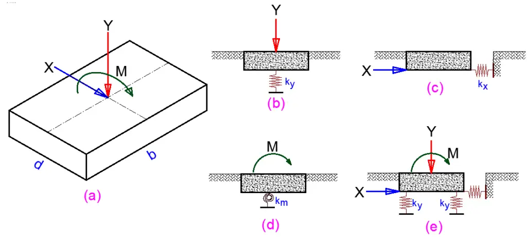
Researchers have presented methods for determining the stiffnesses of shallow footing foundations based on the theory of an elastic half-space (Figure 4). Hambly (1991) generated approximate stiffness estimates by simplifying the equations from these methods. For shallow footings that may slide or tilt across the shorter direction, these simplified formulae are provided below.
Shear modulus: G = E/2(1 + υ)
Vertical stiffness: Ky = 2.5GA0.5/(1 – υ)
Horizontal stiffness: Kx = 2G(1 + υ)A0.5
Rocking stiffness: Km = 2.5GZ/(1 – υ)
where G is the shear modulus of soil; E is Young’s modulus of soil; υ is Poisson’s ratio of soil; A is the foundation area and Z is the foundation section modulus. Vertical and rotational stiffnesses can be more conveniently represented by two parallel springs as shown in Figure 4(e) for which the stiffness is taken as K = 0.5Kz. The parallel springs are spaced at a distance l given by l = 2(Km/Kz)0.5.
Although these equations are approximate, they can be used to quickly determine the order of magnitude of foundation stiffnesses. The load path and courses of reactive forces determine the stiffness of the earth beneath a foundation. Vertical soil responses will occur at vast depths as a result of the vertical loads on the foundations.
Under arching action, on the other hand, the horizontal force and moment on one foundation will be cancelled out by an equal and opposite force and moment on the second foundation, potentially increasing the horizontal stiffness of the soil if the foundations are near enough together. When horizontal breaking forces cause imbalanced reactions in the foundations, concurrent loading on neighbouring foundations reduces the horizontal stiffness of the foundation. Because of these and other difficulties, it is not always possible to account for them when choosing foundation stiffness.
Three-dimensional finite-element analysis can be used to investigate the stiffnesses of foundations for bridges across difficult ground conditions in great detail. Finite-element systems are now available that can describe soils with complex nonlinear stress-strain behaviour and concurrent pore water pressures. Soil data of adequate quality, which is required by advanced computer programmes, is usually scarce.
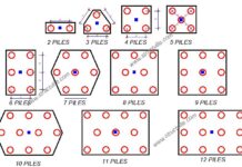
Pile foundation is usually employed when the stable soil stratum is at some depth below the ground level. Wooden piles, concrete piles, steel sections, and steel tubes filled with concrete have all been used in the foundation of bridges. The stiffness of pile foundations is more challenging, especially if the stiffness is derived from the interaction of pile bending and lateral soil forces rather than axial pile compression. There are various computer programmes that may be used to calculate the stiffnesses of pile groups using finite elements or the elastic half-space theory.
Stiffness moduli of soils for Foundation of Bridges
The Young’s modulus of the soil beneath the foundation is one of many elements that affect foundation stiffness. Grain size, gradation, the mineral content of soil grains, grain shape, soil type, relative density, soil particle arrangement, stress level, and prestress all affect the elastic modulus of granular soils based on effective stresses.
Table 1 shows typical elastic modulus and Poisson’s ratio values for typically consolidated granular soils (Das, 1990). In cohesive soils, the undrained elastic modulus is primarily determined by soil plasticity and overconsolidation. The slope of a stress-strain curve generated from an undrained triaxial test can be used to calculate the elastic modulus of soils (Holtz and Kovacs, 1981).
Table 1: Typical elastic modulus and Poisson’s ratio values for typically consolidated granular soils (Das, 1990)
| Type of soil | Elastic modulus (MPa) | Poisson’s ratio |
| Loose sand | 10 – 24 | 0.2 – 0.4 |
| Medium dense sand | 17 – 28 | 0.25 – 0.4 |
| Dense sand | 35 – 55 | 0.30 – 0.45 |
| Silty Sand | 10 – 17 | 0.20 – 0.40 |
| Sand and gravel | 69 – 170 | 0.15 – 0.35 |
To obtain soil stiffnesses, one must first identify the soil parameters through site inspection. This is difficult since testing on tiny samples rarely yields accurate information on huge soil masses. Large-diameter plate bearing tests and back-analyses of observations of identical structures on similar ground conditions are the best ways to determine stiffnesses. Elastic modulus and Poisson’s ratio are not constants for a soil, but rather variables that roughly represent its behaviour under a given set of stresses. For any other set of stresses, other elastic modulus and Poisson’s ratio values will apply.
When determining the values of these factors, good judgement is required. It is difficult to determine elastic modulus values with great precision, hence test data for the specific soil will be required anytime an exact estimate is required. Tangent modulus and secant modulus are phrases that are commonly used. For preliminary analyses of soil-structure interaction, textbooks provide specific direction and information. Calculations should, however, be backed up by examinations of the individual site and foundation conditions at the final design stage.
Worked Example
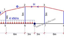
Let us consider for example the foundations for the portal frame shown in Figure 5. The footings for the portal frame have d = 3m (parallel to span) and b = 14m wide. Hence:
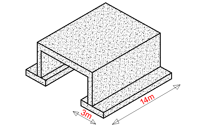
Footing area, A = 14 × 3 = 42 m2
Section modulus of the footing, Z = bd2/6 = (14 × 32)/6 = 21 m3
The stiffnesses, with Poisson’s ratio in the order of 0.3 to 0.5, can be calculated approximately as:
Ky = 1.5E(A)0.5 = 1.5E(42)0.5 = 9.721E
Kx = E(A)0.5 = E(42)0.5 = 6.481E
Km = 1.5EZ = 1.5E(21) = 31.5E
For an assumed value of E = 100 MPa, we find that;
Ky = 927.1 MN/m,
Kx = 648.1 MN/m and
Km = 3150 MN/m
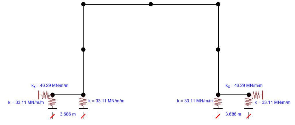
The total width of the foundation is 1m and stiffnesses per unit width are calculated as:
Ky = 927.1/14 = 66.22 MN/m/m
Kx = 648.1/14 = 46.29 MN/m/m
Km = 3150/14 = 225 MN/m/rad/m
Stiffnesses Ky and Km are represented by two parallel springs of:
K = 0.5Ky = 33.11 MN/m/m at a spacing of l = 2(Km/Ky)0.5 = 2(225/66.22)0.5 = 3.686 m
References
[1] Das B. M. (1990) Principles of Foundation Engineering, 2nd edn. PWS-Kent, Boston, MA.
[2] Hambly E. C. (1991) Bridge Deck Behaviour. E & FN Spon, London.
[3] Holtz R. D. and Kovacs W. D. (1981) An Introduction to Geotechnical Engineering. Prentice-Hall, Englewood Cliffs, NJ.

