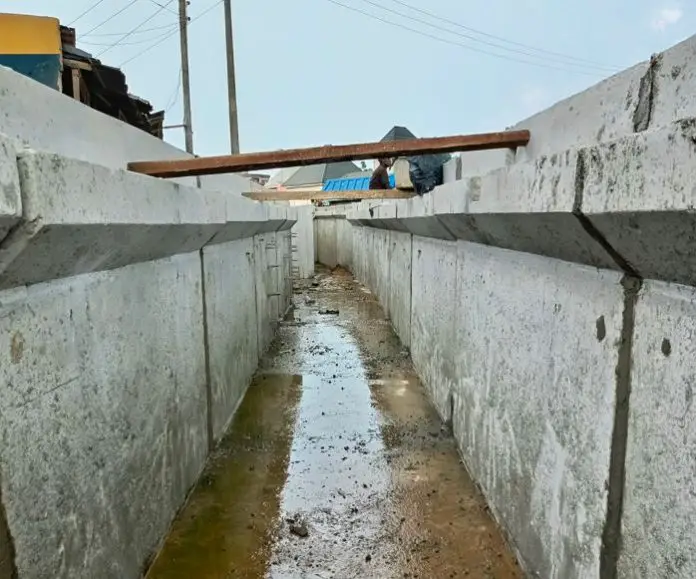
The major objective in the design of an open channel highway drainage structure lies in establishing the optimal hydraulic performance. This process ensures the selection of a structure size that is not only economical but also adequate in conveying the anticipated stormwater runoff. Achieving this balance involves a good understanding of the hydraulic parameters that influence stormwater flow and runoff.
Beyond economic and size considerations, the design of open channel drainage structures must adhere to specific hydraulic requirements. These requirements are instrumental in preventing detrimental outcomes within the drainage system, such as erosion along channel walls or the undesirable accumulation of sediment within the hydraulic structure itself.
Uncontrolled erosion of the drainage structure and linings can compromise the structural integrity of the drainage system, leading to costly repairs and potential safety hazards. Similarly, sediment buildup within the structure can impede its flow capacity, potentially leading to localized flooding during heavy precipitation events.

The proper establishment of the hydraulic requirements for such strucures enables engineers to design open channel drainage systems that effectively manage stormwater runoff while safeguarding the system’s longevity and functionality.
Design of Open Channels
One important design consideration for open channel highway drainage involves achieving an optimal flow velocity. This velocity should be neither excessively low, which could lead to undesirable sediment deposition within the channel, nor excessively high, which could cause erosion of the channel lining itself. The optimum velocity range depends on several factors:
Channel Geometry: The shape and size of the channel significantly influence flow dynamics. A wider and deeper channel can accommodate higher velocities without experiencing erosion compared to a narrower or shallower one.
Channel Lining: The type of material used to line the channel also plays a role. Concrete or riprap linings can withstand higher velocities compared to bare soil channels, which are more susceptible to erosion.
Flow Rate: The quantity of water being transported by the channel is another critical factor. Higher flow rates necessitate a higher velocity to maintain efficient drainage, but exceeding the recommended limits for the specific channel lining can lead to erosion.
Sediment Characteristics: The type of material suspended in the water also influences the optimal velocity. Fine-grained sediments are more prone to deposition at lower velocities, whereas coarser materials can withstand higher velocities without significant erosion risk.
Considering these factors, a channel gradient range of 1% to 5% is generally recommended for achieving the desired flow velocity. Slopes below 1% often result in excessively low velocities, leading to sediment buildup. Conversely, slopes exceeding 5% can generate velocities that cause erosion of even the most robust channel linings.
The design must also account for the discharge point where the drainage channel meets the natural waterway. A significant elevation difference between the channel outlet and the waterway can necessitate additional design considerations, such as the inclusion of energy dissipation structures to prevent scouring and erosion at the discharge point.
Design Principles
The basis of hydraulic design for drainage ditches lies in establishing the minimum cross-sectional area of the channel. This area must be sufficient to convey the anticipated stormwater runoff from a specific design storm event without causing overflow. Achieving this objective involves some calculations to determine the channel’s capacity.
Manning’s formula is one of the most commonly employed methods for calculating a channel’s capacity. This equation was developed on the fundamental assumption of uniform, steady flow within the channel.
v = 1.486/n × R2/3 × S1/2
Based on this assumption, Manning’s formula allows for the calculation of the average velocity (V) within the channel using the following parameters:
v = average discharge velocity (ft /sec)
R = mean hydraulic radius of flow in the channel (ft) = a/p
a = channel cross-sectional area (ft2)
P = wetted perimeter (ft)
S = longitudinal slope in channel (ft /ft)
n = Manning’s roughness coefficient
- Manning’s roughness coefficient (n): This coefficient accounts for the frictional resistance exerted by the channel walls and lining material. Manning’s roughness depends on the type of material used to line the surface of the ditch. Rougher surfaces have higher n values, signifying greater resistance to flow.
- Hydraulic radius (R): This parameter represents the ratio of the channel’s wetted area (the area of the channel in contact with flowing water) to its wetted perimeter (the length of the channel perimeter in contact with flowing water). A larger hydraulic radius translates to a more efficient flow conveyance.
- Channel slope (S): This represents the inclination of the channel bed, expressed as a decimal slope (e.g., 0.02 for a 2% slope). Steeper slopes generate higher velocities.
Typical ranges of Manning’s roughness coefficient for open channels are provided in the Table below.
| Material | Surface Description | Range of Manning’s coefficient n |
| Concrete | All sides formed, no finish | 0.013 – 0.017 |
| Concrete | Trowel finish | 0.012 – 0.014 |
| Concrete | Float finish | 0.013 – 0.015 |
| Concrete | Float finish, some gravel on bottom | 0.015 – 0.017 |
| Concrete | Steel formwork | 0.011 |
| Concrete | Wooden formwork | 0.015 |
| Concrete | Gunite, good section | 0.016 – 0.019 |
| Asphalt | smooth | 0.013 |
| Asphalt | Rough | 0.016 |
By incorporating these parameters into Manning’s formula, engineers can determine the average flow velocity within the drainage ditch. This velocity, combined with the desired design discharge (flow rate) for the storm event, allows for the calculation of the minimum required cross-sectional area to ensure proper drainage without overflow.
The flow in the channel is then given as;
Q = va = 1.486/n × a × R2/3 × S1/2
Types of Flow in Open Channel Hydraulic Structures
Since Manning’s formula was developed on the assumption of steady flow, it is therefore imperative to briefly discuss these types of flow. Open channel flow behaviour can be categorized into two primary classifications: steady and unsteady flow. Steady flow signifies a constant rate of discharge over time, whereas unsteady flow exhibits variations in discharge with time. Steady flow can be further subdivided based on channel characteristics into uniform and non-uniform flow.
Uniform flow manifests when the channel properties, such as slope, roughness, and cross-section, remain consistent along its entire length. Conversely, non-uniform flow occurs when these properties exhibit variations along the channel. In a scenario of uniform flow, the depth (d) and velocity (v) are considered “normal,” and the water surface slope perfectly aligns with the channel bed slope.
Achieving complete uniformity in channel properties across its entire length is a significant engineering challenge in real-world applications. However, Manning’s equation remains a valuable tool for practical solutions to highway drainage problems. This is because, in most cases, the resulting error associated with assuming uniform flow is negligible.
Another key distinction in open channel flow is the characterization of tranquil and rapid flow regimes. Tranquil flow resembles the movement of water in an open channel with a gentle longitudinal slope. In contrast, rapid flow is analogous to water cascading down a steep incline. The flow depth at which a channel transitions from tranquil to rapid flow is termed the critical depth.
When the flow depth exceeds the critical depth, the flow is classified as subcritical. This type of flow is frequently observed in streams traversing plains and broad valleys. Conversely, supercritical flow occurs when the flow depth falls below the critical depth and is often encountered in steep flumes and mountain streams. The critical depth can also be defined as the flow depth corresponding to the minimum specific energy of the system. Notably, the critical depth depends solely on the channel geometry and discharge.
The velocity and channel slope corresponding to uniform flow at critical depth are designated as critical velocity and critical slope, respectively. Therefore, during supercritical flow, the actual flow velocity and channel slope surpass the critical values, while they remain lower than the critical values during subcritical flow.

Design of an Open Channel
Designing an efficient and cost-effective open channel drainage for a highway involves a two-step process:
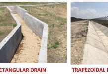
- Channel Sizing for Flow Capacity: The first step entails determining the optimal cross-sectional area for the channel. This area should effectively and economically convey the anticipated stormwater runoff generated by the design storm event to a designated natural waterway.
- Erosion Protection Evaluation: The second step focuses on assessing the channel’s necessity for erosion protection measures. If erosion is a potential concern, this step involves selecting the most appropriate type of lining material to safeguard the channel from scour and degradation.
The Manning formula plays an important role in the first step of channel sizing. By assuming a specific cross-section for the channel and solving the formula, engineers can determine whether the proposed channel is sufficiently large to accommodate the design storm runoff.
This solution can be obtained through manual calculations or by utilizing the relevant Federal Highway Administration (FHWA) charts. The following example will demonstrate both approaches for solving the Manning’s formula in this context.
Design Example
Determine a suitable cross section for a channel to carry an estimated runoff of 290 ft3/sec (8.21 m3/sec) if the slope of the channel is 2% and Manning’s roughness coefficient, n, is 0.015.
Solution:
Select a channel section and then use Manning’s formula to determine the flow depth required for the estimated runoff.
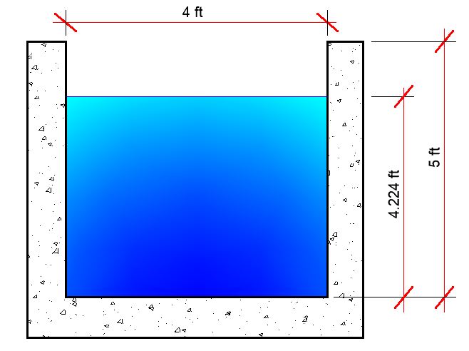
Assume a rectangular channel 4 ft (1.2m) wide.
Flow depth = d
Cross-sectional area (a) = 4d
Wetted perimeter (p) = 4 + 2d
Hydraulic radius R = a/p = 4d/(4 + 2d)
Q = va = 1.486/n × a × R2/3 × S1/2
290 = (1.486/0.015) × 4d × [4d/(4 + 2d)]2/3 × (0.02)1/2
Solving this equation can be complex, but a little consideration will show that d = 4.224 ft satisfies the equation.
(1.486/0.015) × (4 × 4.224) × [4 × 4.224/(4 + 2 × 4.224)]2/3 × (0.02)1/2 = 290 ft3/sec
The solution derived from the Manning formula indicates that for a rectangular channel with a width of 4 ft to effectively convey the anticipated design storm runoff of 390 ft³, the channel must possess a minimum depth of 4.224 ft. However, an additional safety factor is incorporated by providing a freeboard of at least 1 ft above the calculated water depth.
This freeboard serves as a buffer zone to accommodate potential fluctuations in flow rate or debris accumulation within the channel. Consequently, the final design depth for this channel can be established as 5 ft.
Critical Depth
It’s important to note that the specific formula for determining the critical depth (minimum depth for efficient flow) in a rectangular channel is yc = [q2/g]1/3. Where q is the flow per foot of width, in cfs/ft and g is 32.2 ft /sec2. In this problem,
yc = [(290/4)2/32.2]1/3 = 5.46 ft
Since the critical depth is greater than the depth of flow, the flow is supercritical.
For the geotechnical and structural design of the drainage channel, check the link below;
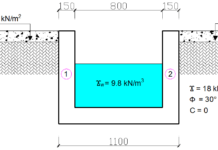
Geotechnical and Structural Design of Rectangular Roadside Drains
Selecting Optimal Channel Lining
Traditionally, the selection of lining material for drainage channels has relied on ensuring a flow velocity below a specific “permissible velocity” threshold to prevent erosion of the lining. However, advancements in research have revealed a more effective approach. For flexible linings, the selection criterion should prioritize the concept of “maximum permissible depth of flow” (dmax). This parameter establishes the maximum water depth the lining can safely accommodate before succumbing to erosion.
In contrast, rigid channels constructed from materials like concrete or soil-cement exhibit minimal erosion concerns under typical highway traffic conditions. Consequently, these rigid channels lack a defined maximum permissible depth based on erosion control. The primary factor influencing the final design depth for rigid channels becomes the required freeboard – the vertical distance maintained between the water surface and the top of the channel bank for safety purposes.

