Roadside drains or channels are structures that are used for conveying storm water away from roads or streets. The complete design of rectangular roadside drains involves hydraulic design, geotechnical design, and structural design.
The hydraulic design involves the proper sizing of the drain to ensure that the design flood is properly discharged, while the geotechnical design involves the verification of the capacity of the supporting soil to carry the weight of the channel and the water. It also involves the verification of the soil-structure interaction since drains are buried structures. The structural design of drains involves the selection of the proper material, thickness, and reinforcement to withstand the pressures and forces exerted by the soil and water.
In previous articles, we extensively discussed how to determine the best hydraulic cross-section of roadside drains and the construction and cost comparison of rectangular and trapezoidal drains. In this article, you will discover everything you need to know about the geotechnical and structural design of rectangular roadside drains.
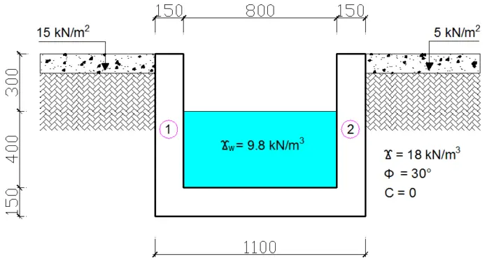
Similar to the design of retaining walls, roadside drains are also subjected to active and earth pressures. In the example treated below, active and passive earth pressures, surcharge loads and water pressures are considered.
Worked Example on the Design of Rectangular Roadside Drains
The rectangular drain shown below is backfilled with a typical cohesionless granular material, having a unit weight (γ) of 18 kN/m3, zero cohesion (C), and internal angle of friction (ϕ) of 30°. The allowable bearing pressure of the soil is 150 kN/m2, the coefficient of friction (μ) is 0.5, the unit weight of reinforced concrete is 24 kN/m3, and surcharge loads of 15 and 5 kN/m2 on both sides of the drain. The drain has been designed to cater to a flow of 400mm depth and the unit weight of water (γw) should be taken as 9.8 kN/m3.
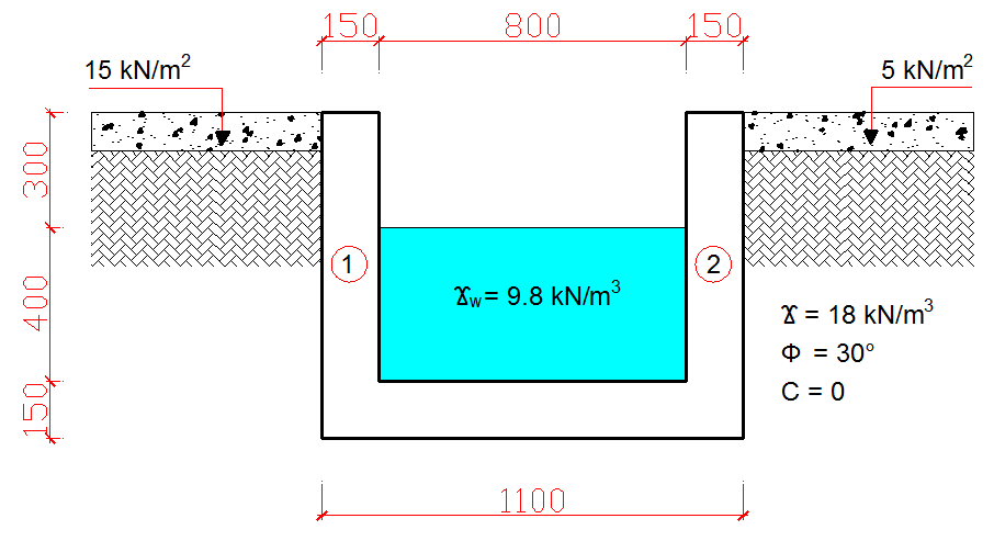
Given the information above, design the drain wall and base reinforcements assuming fcu = 20 N/mm2, fy = 460 N/mm2, cover to reinforcement = 40 mm, diameter of reinforcements = 10 mm, and thickness of walls and base = 150 mm.
Geotechnical Design
Wall pressure calculations
Ka = (1 – sinϕ) / (1 + sinϕ)
Ka = (1 – sin30°) / (1 + sin30°) = 0.333
Wall 1
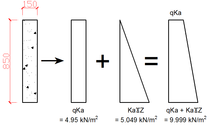
Active pressure at the top of the drain wall = qKa = 15 × 0.33 = 4.95 kN/m2
Active pressure at the base of the drain wall = qKa + KaγZ = 4.95 + (0.33 × 18 × 0.85) = 4.95 + 5.049 = 9.999 kN/m2
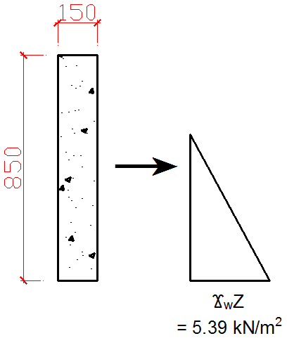
Passive pressure at the top of the drain wall = 0
Passive pressure at the base of the wall = γwZ = (9.8 × 0.55) = 5.39 kN/m2
Net pressure at the base of the wall = 9.999 – 5.39 = 4.609 kN/m2
Wall 2
Active pressure at the top of the drain wall = qKa = 5 × 0.33 = 1.65 kN/m2
Active pressure at the base of the drain wall = qKa + KaγZ = 1.65 + (0.33 × 18 × 0.85) = 1.65 + 5.049 = 6.699 kN/m2
Passive pressure at the top of the drain wall = 0
Passive pressure at the base of the wall = γwZ = (9.8 × 0.55) = 5.39 kN/m2
Net pressure at the base of the wall = 6.699 – 5.39 = 1.309 kN/m2
Total vertical load (N)
Walls (Wws) = 2(0.15 x 0.7 x 24) = 5.04 kN/m
Base (Wb) = 1.1 x 0.15 x 24 = 3.96 kN/m
Water (Ww) = 0.4 x 0.8 x 9.8 = 3.136 kN/m
Total vertical load Wws + Wb + Ww (N) = 5.04 + 3.96 + 3.136 = 12.136 kN/m
Horizontal forces on drain walls due to surcharge load and backfill
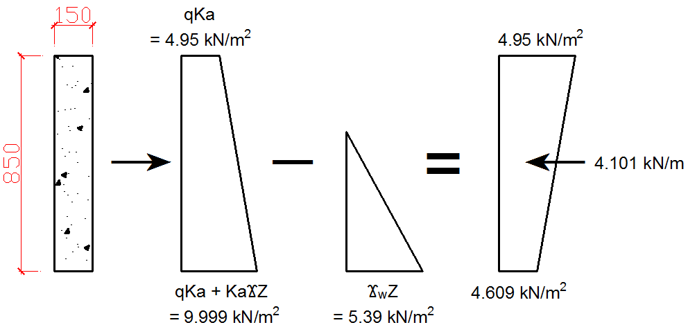
Wall 1 = qKaZ + (0.5 × KaγZ × Z) – (0.5 × γwZ × Z) = (15 × 0.333 × 0.85) + (0.5 × 5.049 × 0.85) – (0.5 × 5.39 × 0.85) = 4.246 + 2.146 + 2.291 = 4.101 kN/m
Wall 2 = qKaZ + (0.5 × KaγZ × Z) – (0.5 × γwZ × Z) = (5 × 0.33 × 0.85) + (0.5 × 5.049 × 0.85) – (0.5 × 5.39 × 0.85) = 1.403 + 2.146 – 2.291 = 1.258 kN/m
Net horizontal force (PA) = 4.101 – 1.258 = 2.843 kN/m
Resistance to sliding
Frictional Force (Ff) = μN = 0.5 × 12.136 = 6.068 kN/m
F.O.S = Ff / PA = 6.068/2.843 = 2.134
The factor of safety 2.134 > 1.5. Therefore, the drain is very safe from sliding.
Resistance to overturning
Taking moment about wall 1;
Sum of overturning moments (Mo) = (4.101 – 1.258) × (0.85/3) = 0.806 kNm per m
Sum of restoring moments (MR) = (W1 × 0.075m) + (Ww × 0.55m) + (W2 × 1.025) + (Wb × 0.55) = (2.52 × 0.075) + (3.136 × 0.55) +(2.52 × 1.025) + (3.96 × 0.55) = 0.189 + 1.725 + 2.583 + 2.178 = 6.675 kNm/m
F.O.S = MR / MO = 6.675/0.806 = 8.281
The factor of safety 8.281 > 2. Therefore, the drain is very safe from overturning.
Bearing capacity check
Bending moment about the centerline of the base;
M = (W2 × 0.475m) + (4.101 × 0.85/3) – (W1 × 0.475m) – (1.258 × 0.85/3) = (2.52 × 0.475m) + (4.101 × 0.85/3) – (2.52 × 0.475m) – (1.258 × 0.85/3) = 1.197 + 1.162 – 1.197 – 0.356 = 0.806 kNm per m
Total vertical load (N) = 12.136 kN/m
Eccentricity (e) = M/N = 0.806/12.136 = 0.066m
Check: D/6 = 1.1/6 = 0.183m
Since e < D/6, there is no tension in the drain base.
Maximum pressure in the drain base (qmax) = P/B (1 + 6e/B) = 12.136/1.1 [1 + (6 × 0.066)/1.1] = 15.005 kN/m2
Minimum pressure in the drain base (qmin) = P/B (1 – 6e/B) = 12.136/1.1 [1 – (6 × 0.066)/1.1] = 7.061 kN/m2
Since qmin and qmax are lower than the allowable bearing pressure of the soil (150 kN/m2), bearing capacity check is satisfied.
Structural Design
Design of the Walls
Since the horizontal force due to surcharge load and backfill on Wall 1 > Wall 2, we adopt Wall 1 parameters for design. Using the centroid formula of a parallelogram for the pressure diagram of wall 1 to determine the distance (x) from the centroid to the base of the wall and distance (y) from the centroid to the top of the wall;
x = 0.85 [((4.609 + (2 x 4.95)) / (3(4.609 + 4.95))] = 0.43m
Thus, y = 0.85 – 0.43 = 0.42m
Taking moment at the top of the drain wall due to the active force;
M = 4.101 x 0.42 = 1.722 kNm per m
Taking moment at the base of the drain wall due to the active force;
M = 4.101 x 0.43 = 1.763 kNm per m
Since the moment at the base of the drain wall is greater than that at the top, we adopt the moment at the base for design.
At ultimate limit state;
M = 1.4 × 1.763 = 2.468 kNm per m
Flexural Design (Bending)
Given: Thickness of wall (h) = 150mm, Cover = 40mm, fcu = 20 N/mm2, fy = 460N/mm2, Rebars = 10mm
Effective depth (d) = 150 – 40 – (10/2) = 105 mm
K = M/(fcubd2) = (2.468 x 10⁶) / (20 x 1000 x 1052) = 0.0112 (K < 0.156)
la = 0.5 + (0.25 – k/0.9)0.5 = 0.5 + (0.25 – 0.0112/0.9)0.5 = 0.987
Since 0.987 > 0.95, la = 0.95
As,req = M/(0.95fy.la.d) = (2.468 x 10⁶) / (0.95 × 460 x 0.95 x 105) = 56.62 mm2/m
ASmin = (0.13bh)/100 = (0.13 x 1000 x 150) / 100 = 195 mm2
Provide Y10 @ 300mm c/c (ASprov = 260 mm2/m)
Steel ratio check
4.0 > (100ASprov / bh) > 0.13
4.0 > (100 x 260) / (1000 x 150) > 0.13
4.0 > 0.17 > 0.13 (Steel ratio is satisfied)
Shear check
Ultimate design shear force on drain wall (V) = (1.4 × 4.101) = 5.741 kN/m
Shear stress (v) = V/bd = (5.741 × 1000) / (1000 × 105) = 0.055 N/mm2
Shear strength (vc) = 0.632 × (100As/bd)1/3 × (400/d)1/4 × (fcu/25)1/3
vc = 0.632 × [(100 × 260)/(1000 × 105)]1/3 × (400/302)1/4 × (20/25)1/3 = 0.632 × 1.3529 × 1.3971 × 0.9283 = 1.109 N/mm2
Since v < vc, no shear reinforcement required.
Design of the base
The pressure distribution diagram on the base at serviceability limit state is shown below;
qmin = 7.061 kN/m2
qmax = 15.005 kN/m2
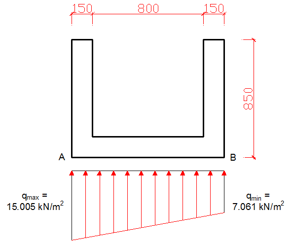
At the ultimate limit state;
qmin = 7.061 x 1.4 = 9.885 kN/m2
qmax = 15.005 x 1.4 = 21.007 kN/m2
On investigating the maximum design moment at point A;
Water = 1.4 × [9.8 × 0.4 × 0.8 × (0.8/2 + 0.15) = 2.415 kNm/m
Base = 1.4 × [24 × 0.15 × 0.8 × (0.8/2 + 0.15) = 2.218 kNm/m
Earth pressure = [9.885 × 1.1 × (1.1/2)] + [(21.007 – 9.885) × 1.1 x 0.5 × (1.1/3)] = 8.223 kNm/m
Net moment = 8.223 – 2.415 – 2.218 = 3.59 kNm/m
On investigating the maximum design moment at point B;
Water = 2.415 kNm/m
Base = 2.218 kNm/m
Earth pressure = [9.885 × 1.1 × (1.1/2)] + [(21.007 – 9.885) × 1.1 × 0.5 × (2 × 1.1/3)] = 10.466 kNm/m
Net moment = 10.466 – 2.415 – 2.218 = 5.833 kNm per m
Since net moment at B > moment at A, we adopt 5.8833 kNm for design.
Flexural Design (Bending)
Given: Thickness of base(h) = 150 mm, Cover = 40 mm, fcu = 20 N/mm2, fy = 460 N/mm2, Size of rebars = 10mm
Effective depth (d) = 150 – 40 – (10/2) = 105mm
K = M/(Fcubd2) = (5.833 × 10⁶) / (20 × 1000 × 1052) = 0.0265 (K < 0.156)
la = 0.5 + (0.25 – k/0.9)0.5 = 0.5 + (0.25 – 0.0265/0.9)0.5 = 0.97
Since 0.97 > 0.95, La = 0.95
ASreq = M/(0.95Fy.La.d ) = (5.833 × 10⁶) / (0.95 × 460 × 0.95 × 105) = 133.82 mm2/m
ASmin = (0.13bh)/100 = (0.13× 1000 × 150) / 100 = 195 mm2
Provide Y10 @ 300mm c/c (ASprov = 260 mm2/m)
Shear Check
Calculating the maximum shear force at any section of the drain base;
Water = 1.4 × (9.8 × 0.4 × 0.8) = 4.39 kN/m
Base = 1.4 × (24 × 0.15 × 0.8) = 4.032 kN/m
Earth pressure = 0.5 × (21.007 + 9.885) × 0.8 = 12.356 kN/m
Net shear force = 12.356 – 4.39 – 4.032 = 3.934 kN/m
Shear stress (v) = V/bd = (3.934 × 1000) / (1000 × 105) = 0.037 N/mm2
Shear strength (Vc) = 0.632 × (100As/bd)1/3 × (400/d)1/4 × (fcu/25)1/3 = 0.632 × (100 × 260)/(1000 × 105)]1/3 × (400/302)1/4 × (20/25)1/3 = 0.632 × 1.3529 × 1.3971 × 0.9283 = 1.109 N/mm2
Since v < Vc, no shear reinforcement required.
Detailing
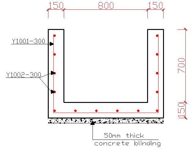
Conclusion
This article has discussed the geotechnical and structural design of rectangular roadside drains. However, readers must note that only one load case has been treated. Therefore, a designer must consider other load cases or load combinations to ascertain the accuracy of the design. For example, it would be appropriate to rerun the design with the drain filled and when the drain is empty to determine the most critical load case or combination.






This is educative.
May God bless the Author
It is very nice topic i like it
Good work. Thank you
Which code is used to design this drain.
great job! please where did you got this 0.55 from the below equation? thanks!
YwZ ( 9.8 X 0.55 ) =5.39
Oyekunle Adekunle Amos; that is the addition of the height of water in the drain and the thickness of the base conc. which is 400mm + 150mm(0.55m) .
Thank you,
Thanks I like the analysis
Sir, I can not understand the formula of
(i). ,M = fcu.k.bd2- is it within IS Code?.Is it working Stress Method or Limit State Method? What is k? What is the Equivalent value of fcu.k.
ii.What is la in for mula M = As*0.95fy*la*d? What ia la = 0.5(0.25 -k/09)^0.5.
Sir, please clear it and which code it satisfy?
Thank You,Sir
Regards:Uttam Kumar Roy
Kolkata, India
The design was done according to BS 8110… Old British standard
2.52 in W1 and W2? why sir?
i messaged you sir in messenger please help me thank you sir
for sum of restoring moments(MR). how you got w1x0.075 and W2x1.025? can you help me. Thanks
what is d=302?
Which section of the article are you referring to?
where did 2.52 for w1and w2 come from
pls how was 1.025 gotten from sum of restoring moment