Airfield pavements are designed and constructed to provide durable all-weather travel surfaces for the safe landing, takeoff, and quick movement of passengers and aircraft while maintaining an appropriate level of comfort for users. During the design and construction phases, considerable consideration is given to the following factors in order to meet these functional requirements for pavements:
(a) selection of pavement type,
(b) selection of materials to be used for various pavement layers and treatment of subgrade soils,
(c) structural thickness design for pavement layers,
(d) subsurface drainage design for the pavement system,
(e) surface drainage and geometric design, and
(f) rideability of the pavement surface.

Realistic methods for evaluating the loading characteristics of aircraft and the structural reaction of the pavement are necessary for the design of an airfield’s pavement. It has long been understood that the gross weights of the aircraft utilizing the pavement, as well as the arrangement, spacing, and tyre pressures of their undercarriage wheels, determine the severity of load-induced stresses in a pavement and subgrade.
Due to changes in traffic operations and functional applications of the pavements, the traffic loading analysis process for airport pavements differs slightly from that for highway pavements. The steps in the traffic loading analysis of airfield pavements include;
- Estimation of expected initial year traffic volume
- Estimation of expected annual traffic growth rate
- Estimation of traffic stream composition
- Computation of traffic loading
- Estimation of design traffic loading for different functional areas
The information on the first two steps may be obtained from the planning forecast of the relevant airport authority.
Traffic Stream Composition
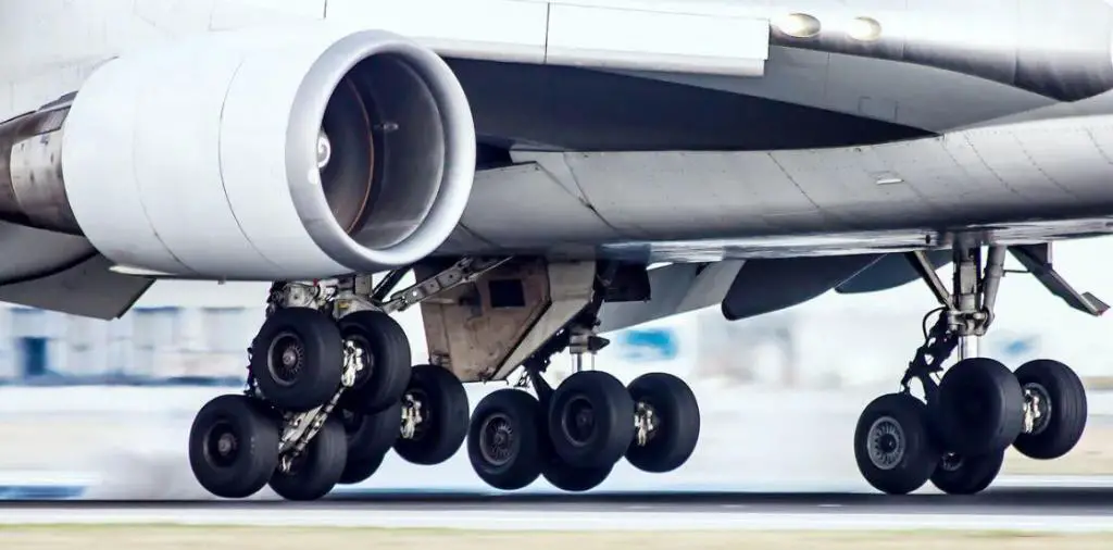
The nose gear and main landing gear of an aircraft transfer the weight of the aircraft to the pavement. The typical wheel arrangements on the main landing gear legs of civil aircraft are shown in Figure 2. For the purpose of pavement design, it is necessary to identify the types of aircraft, landing gear details, and their relative frequencies of arrival. This is because different aircraft have varied gross weights and wheel configurations.

Computation of Traffic Loading
The maximum takeoff weights of the aircraft are typically taken into account when designing pavement. It is also typical to assume that the main landing gears carry 95% of the aircraft’s gross weight and the nose gear carries 5%. Both the equivalent load idea and Miner’s hypothesis have been used in the analysis of mixed traffic loading.
For instance, the FAA method [Federal Aviation Administration, 1978] uses the variables in Table 1 to convert the annual departure of all aircraft into the equivalent departures of a selected design aircraft. In thi case, the designer should multiply the annual departures of a given aircraft type by the conversion factor to obtain annual departures in design aircraft landing gear.
| Aircraft Type | Design Aircraft | Conversion Factor F |
| Single-wheel | Dual-wheel | 0.8 |
| Single-wheel | Dual-tandem | 0.5 |
| Dual-wheel | Dual-tandem | 0.6 |
| Double dual-tandem | Dual-tandem | 1.0 |
| Dual-tandem | Single-wheel | 2.0 |
| Dual-tandem | Dual-wheel | 1.7 |
| Dual-wheel | Single wheel | 1.3 |
| Double dual-tandem | Dual-wheel | 1.7 |
The FAA uses the equivalent single-wheel load (ESWL) concept to create the thickness design curves for flexible airfield pavements. When designing airfield pavement, the concept of ESWL is frequently used to evaluate the impact of multiple-wheel landing gears.
The control response chosen for ESWL computation, pavement thickness, and the relative stiffness of pavement layers all affect how much ESWL a particular landing gear has. ESWL calculations based on equal deflection (at the surface or at the pavement-subgrade interface) or equal stress (at the bottom face of the bound layer) are frequently used for airport pavement design.
Equal Stress ESWL
A detailed method for calculating the ESWL would require both a correct analytical solution for the required stress produced by the target wheel assembly and a process of trial-and-error to determine the magnitude of the single wheel that will produce the same value of stress. Because of how time-consuming this process is, simplified approaches have been used in practice.
A simplified method for calculating the equal subgrade stress ESWL of a pair of dual wheels for flexible pavement design is shown in Figure 4.

If the pavement thickness is less than or equal to d/2, where d is the lowest edge-to-edge distance between the tire imprints of the dual wheels, the ESWL is equal to one wheel load P with the specified 45° spread of applied pressure.
The method further assumes that ESWL = 2P for any pavement equal to or thicker than 2S, where S is the center-to-center spacing of the dual wheels. For pavement thicknesses between d/2 and 2S, ESWL is determined, as shown in Figure 4, by assuming a linear log–log relationship between ESWL and pavement thickness. Note that d is equal to (S – 2a), where a is the radius of the tyre imprint given by;
a = √(P/πp)
where p is the tyre pressure.
This simplified procedure provides an approximate ESWL estimation for flexible pavements.
In the case of rigid pavements, computation of stresses for equal stress ESWL should be based on rigid slab analysis such as the well-known Westergaard formulas, which give the maximum bending stress σmax and the maximum deflection δmax.
Solved Example
The total load on a set of dual wheels is 45,000 lb. The tire pressure of the wheels is 185 psi. The centre-to-centre spacing of the wheels is 34 in. Calculate the equal stress ESWL if the thickness of the pavement structure is (a) h = 30 in. and (b) h = 70 in.
Solution
Load per wheel = 22,500 lb., radius of tire imprint a = √(22500/185π) = 6.22 in., S = 34 in., and d = (S – 2a) = 21.56.
By means of a log–log plot as shown in Figure 4, ESWL is determined to be 33,070 lb. for h = 30 in. For h = 70 in., since h > 2S, ESWL = 2(22,500) = 45,000 in.
Airfield Pavement Loading in the UK
In the UK, Aircraft Classification Number (ACN) and Pavement Classification Number (PCN) are the two parameters often used in airfield pavement design.
The ACN of an aircraft describes the relative severity of its loading on a pavement supported by a given subgrade. Two mathematical models—one for rigid pavements and the other for flexible pavements—are used to compute ACNs.
For a given limiting stress or the number of load repetitions, the ACN of an aircraft is mathematically defined as twice the single wheel load (expressed in thousands of kilograms) at a standard tyre pressure of 1.25 MPa, which requires the same pavement thickness as the actual main wheel gear of the aircraft. The standard thickness is the pavement’s thickness.
ACN Calculation for Rigid Pavement
The method of calculating ACNs for aircraft on rigid pavements is set out below with reference to Figure 1:

(i) Calculate the reference thickness (tc), the thickness of concrete slab which when loaded at the centre by one main wheel gear of the actual aircraft gives a maximum flexural stress of 2.75 N/mm2 (fct) on a subgrade whose Modulus of Subgrade Reaction (k) is one of the standard values (see (iv)). The mathematical model for the stress calculation is the Westergaard solution for an elastic slab on a dense liquid subgrade (Winkler Foundation). The modulus of elasticity for concrete is taken as 27.6 x 10³ MN/m2 and Poisson’s ratio as 0.15.
(ii) Calculate the single wheel load (WR) which at a tyre pressure of 1.25 MPa induces a flexural stress of 2.75N/mm2, in slab of thickness tc.
(iii) The ACN = 2 x (WR/1000) = WR/500 where WR is in kgs.
(iv) Calculate ACNs for each aircraft for the following four categories of subgrade characterised in terms of a standard k.
| Subgrade Category | k |
| High | 150 MN/m2/m |
| Medium | 80 MN/m2/m |
| Low | 40 MN/m2/m |
| Ultra-low | 20 MN/m2/m |
ACN Calculation for Flexible Pavement
The method of calculating ACNs for aircraft on flexible pavements is set out below with reference to Figure 2:
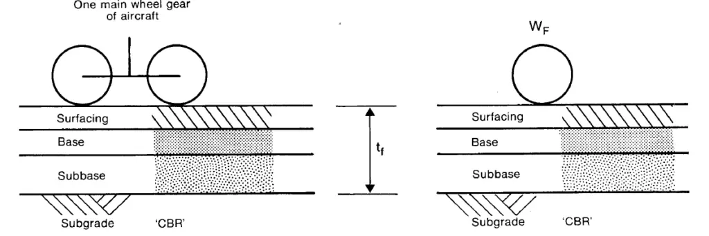
(i) Calculate the reference thickness (tf), the thickness of conventional flexible pavement which allows 10,000* load repetitions by one main wheel gear of the actual aircraft on a subgrade whose CBR is one of the standard values (see (iv)). The method of calculation is based on the CBR Equation and Boussinesq deflection factors.
(ii) Calculate the single wheel load (WF) which at a tyre pressure of 1.25 MPa allows the same 10,000 load repetitions on a flexible pavement of total thickness tf. The calculation is carried out using the following formula:
WF = 0.005tf2/(0.878/CBR – 0.01249)
(iii) The ACN=2 x WF/1000 = WF/500
where WF is in kgs.
(iv) Calculate ACNs for each aircraft for the following four categories of subgrade characterised in terms of a standard CBR.
| Subgrade Category | CBR |
| High | 15% |
| Medium | 10% |
| Low | 6% |
| Ultra-low | 3% |
Pavement Classification Number (PCN)
By the definition of the ACN-PCN method, the PCN is the ACN of the aircraft which imposes a severity of loading equal to the maximum permitted on the pavement of unrestricted use.
PCNs are reported as a five-part code as follows:
Part i: The PCN Number: The highest permitted ACN at the appropriate subgrade category.
Part ii: The type of pavement: R = rigid, F = flexible. If the actual pavement is of mixed construction the engineer will need to decide whether the behaviour and mode of failure of the pavement are likely to be those of a rigid or flexible one, then classify accordingly.
Part iii: The pavement subgrade category:
A = High
B = Medium
C = Low
D = Ultra Low
The ranges of subgrade strength covered by these categories are shown in the Tables above. Note that these strength ranges are not equivalent for rigid and flexible pavements.
Part iv: The maximum tyre pressure authorised for the pavement:
W = High, no limit.
X = Medium, limited to 1.5 MPa (217 psi)
Y = Low, limited to 1.0 MPa (145 psi)
Z = Very low, limited to 0.5 MPa (73 psi)
Part v: Pavement design/evaluation method:
T = Technical design or evaluation
U = By experience of aircraft actually using the pavement
The Design ACN
The design ACN is based on the Design Aircraft; which is normally the aircraft with the highest ACN on the actual subgrade.
The actual weight of aircraft when using the pavement must be considered in determining the design ACN. The Maximum All-Up Weight figure will normally be used, but lighter weights are appropriate where:
(i) the runway length imposes restrictions on the operating weights,
(ii) the pavement is only used by landing aircraft (e.g. fast turn offs) and
(iii) the pavement is only used by unladen aircraft (e.g. the accesses to maintenance hangars).
To compute an ACN at a weight between the published values it is assumed that ACNs vary linearly with weight.
The design ACN should also relate the actual value of the subgrade under a pavement. The ACNs listed in B are for four standard subgrade categories. If the value of actual subgrade is not the same as that of a standard subgrade, the design ACNs are to be calculated by linear interpolation or extrapolation of ACNs for the standard subgrades.
The high category subgrade for flexible pavements is for CBR 15%. When designing pavements for subgrades with CBR greater than 15% the following rules may be applied:
(i) Single and Dual Main Wheel Gears
Take the ACN for CBR >15% to be the same as the ACN for CBR 15%.
(ii) Dual-Tandem Main Wheel Gears
Take the ACN for CBR ≥ 20% as equal to 0.95 x the ACN for CBR 15%. Values for CBRs between 15% and 20% can be obtained by linear interpolation e.g.
ACN for CBR 17% = 0.98 x the ACN for CBR 15%.
(iii) Tridem Main Wheel Gears
Take the ACN for CBR ≥ 20% as equal to 0.97 x the ACN for CBR 15%.
Values for CBRs between 15% and 20% can be obtained by linear interpolation.
For rigid pavements, the effect of the higher subgrade values is less significant and it is, therefore, acceptable to assume that: ACN for k >150 MN/m2/m = ACN for k of 150 MN/m2/m.
For pavements which would subsequently be difficult to strengthen, it may be appropriate to design for a higher ACN e.g. for aprons adjacent to hangars and terminal buildings. Where a design ACN of less than 10 is being considered a check should be made to ensure that the pavement is strong enough for the expected use by aircraft servicing vehicles.
Provided the PCN for a pavement is equal to or greater than the ACN of the aircraft and the operating tyre pressure does not exceed the PCN limitation, unrestricted use of the pavement by that aircraft (or those with lower ACNs) is permitted. The term ‘unrestricted use’ of a pavement is not specifically defined. However, it is a pavement design parameter which should reflect current and forecast use over an appropriate design life before major maintenance is required.


