I came across an Instagram post on the design of reinforced concrete cantilever beams that forms part of a modern residential dwelling. According to the author of the post, the cantilever beam is about 5 m long.
Cantilevers are beams that are rigidly fixed at one end, and freely supported at the other end. By implication, they are very susceptible to excessive deflection and vibration.
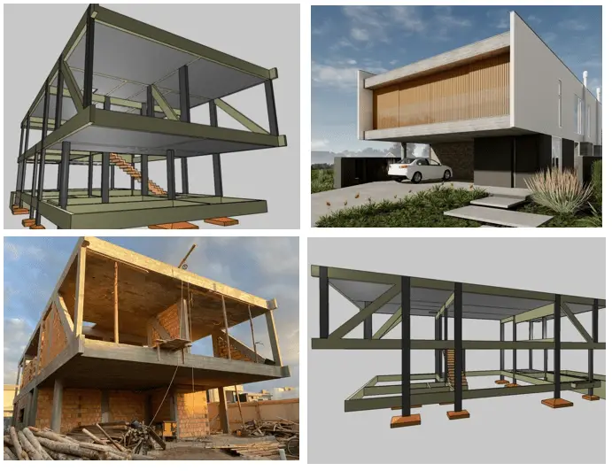
The architectural rendering of the structure in question is shown in Figures 1 and 2.
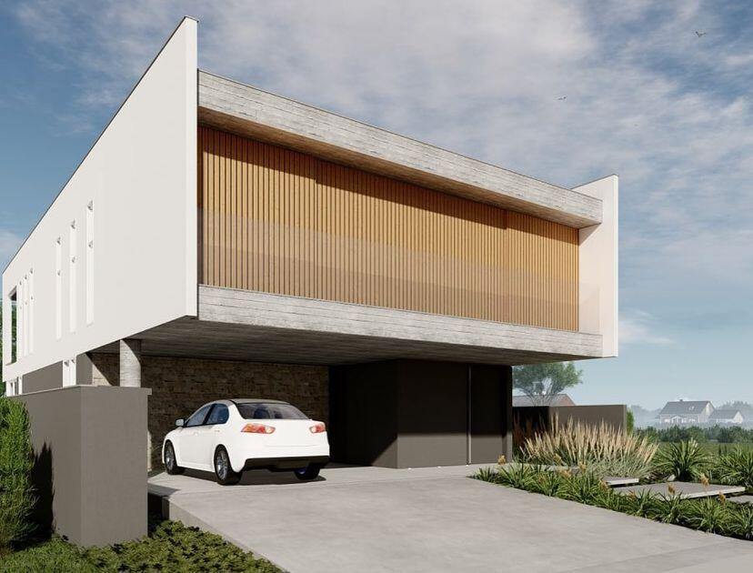
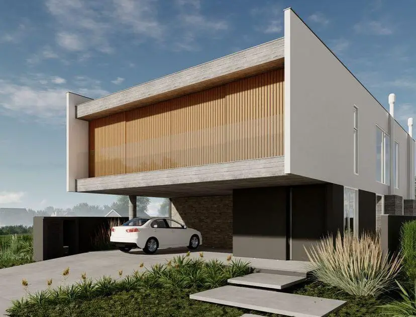
As can be seen from the images above, the architectural rendering depicts a contemporary building with a cantilever projection at the front. To solve the problem, the design engineer, decided to introduce a diagonal/slanted reinforced concrete column, which would act as tension members to support the cantilever beam. The structural modelling of the scheme adopted by the structural engineer is shown in Figures 3 to 5.
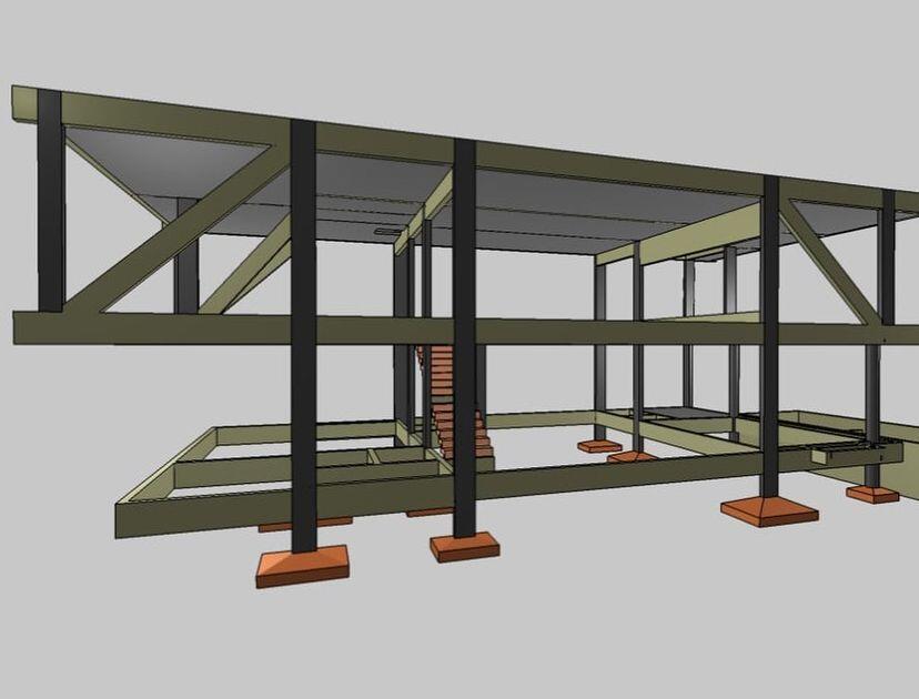

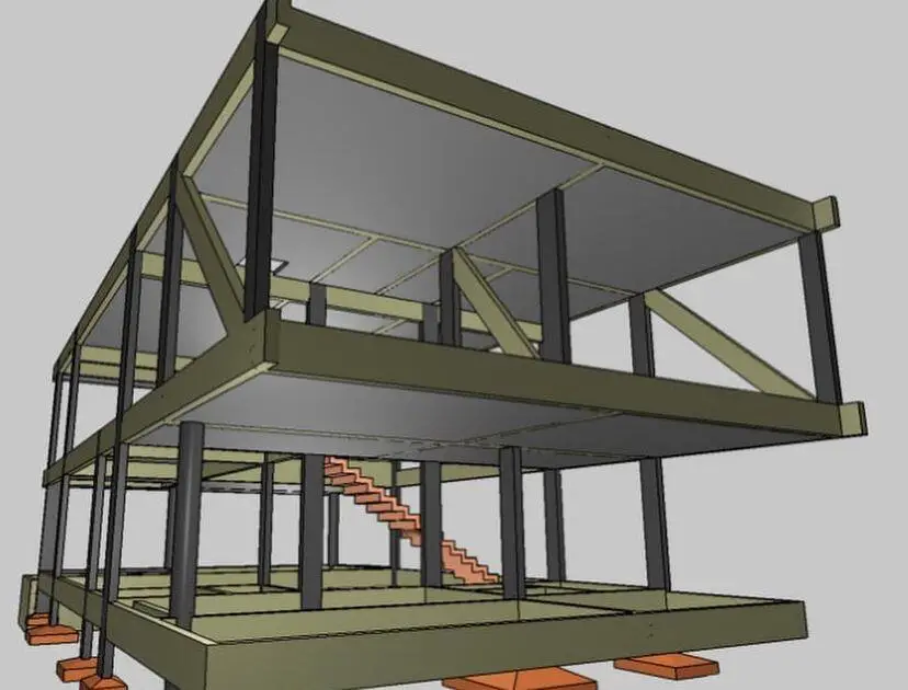
By all indications, the design has been completed and the contractor has gone to the site. The construction images of the models are shown in Figures 5 – 7.
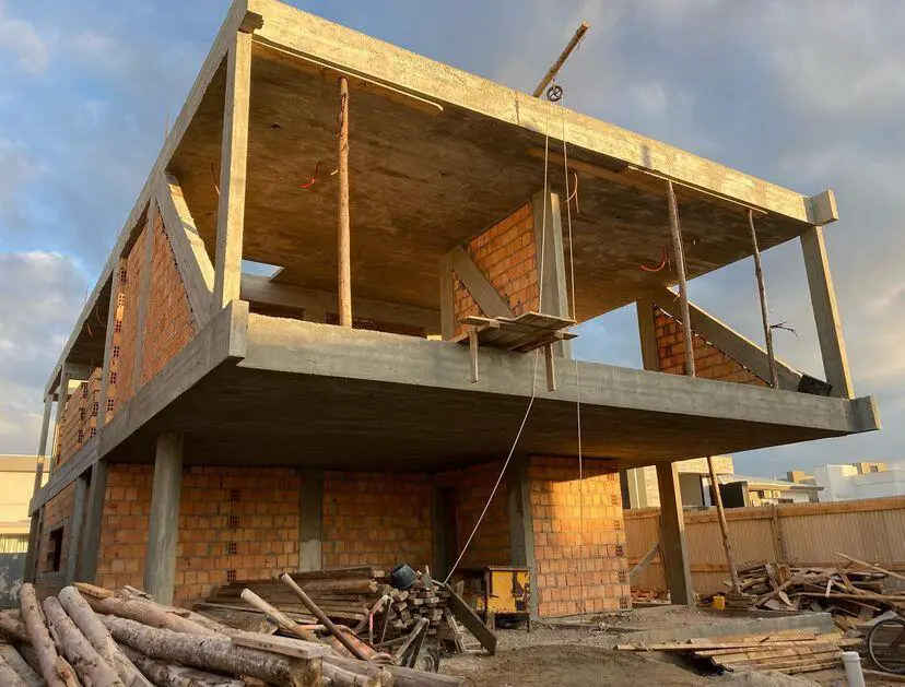
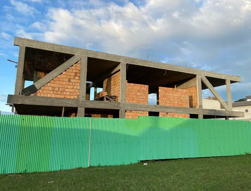
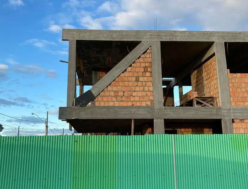
As can be seen in Figure 7, the reinforced concrete diagonal columns were cast monolithically with the frame of the structure. Then bricks were used to cover the openings to create a plain wall that matches the architectural requirements.
Why did the Model Succeed?
The model adopted by the structural engineer succeeded because there are full walls without openings where the inclined columns can be hidden without any implications. Because there are no openings (doors, windows, or curtain walling) on the first bay of the first floor, the inclined columns can be introduced without affecting the architectural concept of the building.
If there had been need for openings in those walls, the adopted structural scheme would not have been an ideal solution. Therefore the ingenuity of the design engineer is appreciated.
How Efficient is the Model?
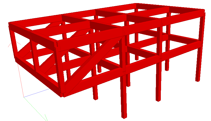
To check the structural efficiency of the model, let us carry out a comparative assessment of a cantilever beam with and without diagonal columns on Staad Pro software. The 3D rendering of the model without diagonal columns is shown in Figure 8.
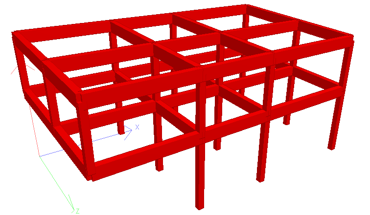
For simplicity, all the first floor beams were loaded with a uniformly distributed load of 25 kN/m as shown below. Furthermore, a uniformly distributed load of 10 kN/m was applied to the roof beams.
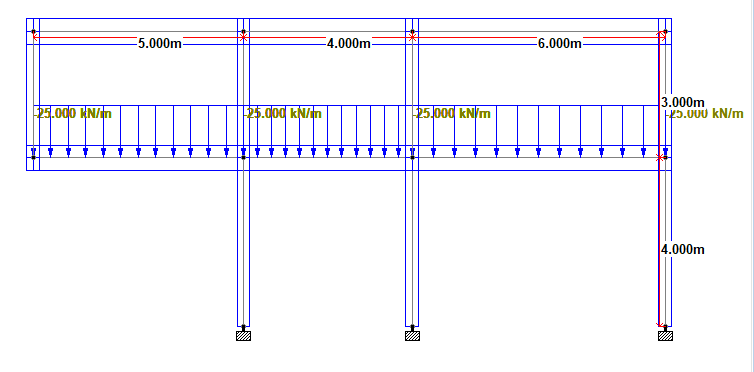
The analysis comparison is going to check the effect of introducing a diagonal column on the deflection, bending, and shear force on the structure.
Analysis Results: Without diagonal column
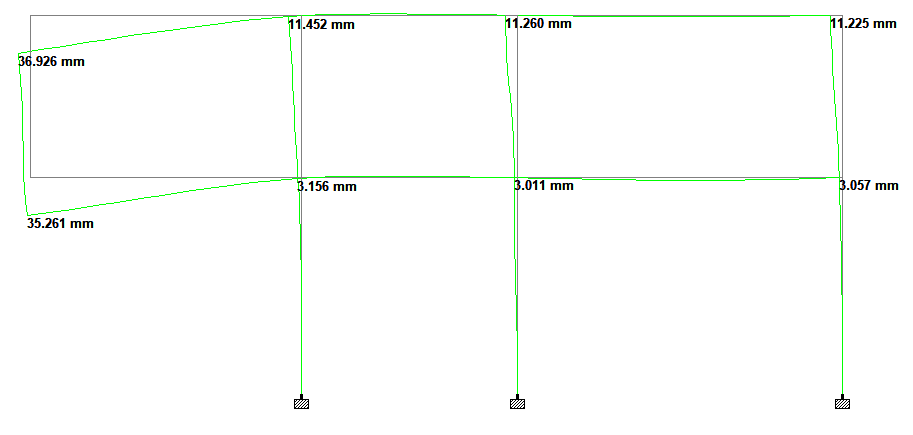
As can be seen above, without the presence of the diagonal columns, the maximum deflection at the free end of the cantilever was 35.261 mm.
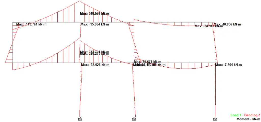
Without the presence of the diagonal column, the maximum cantilever moment was 372.701 kNm. However, the column sitting on top of the cantilever beam appeared to be tension, assisting in supporting the cantilever beams and sending the load to the roof beams.
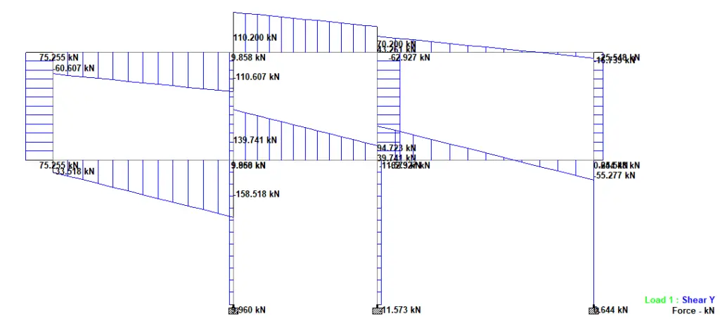
A maximum shear force value of 158.518 kN was observed at the fixed end of the cantilever without diagonal columns.
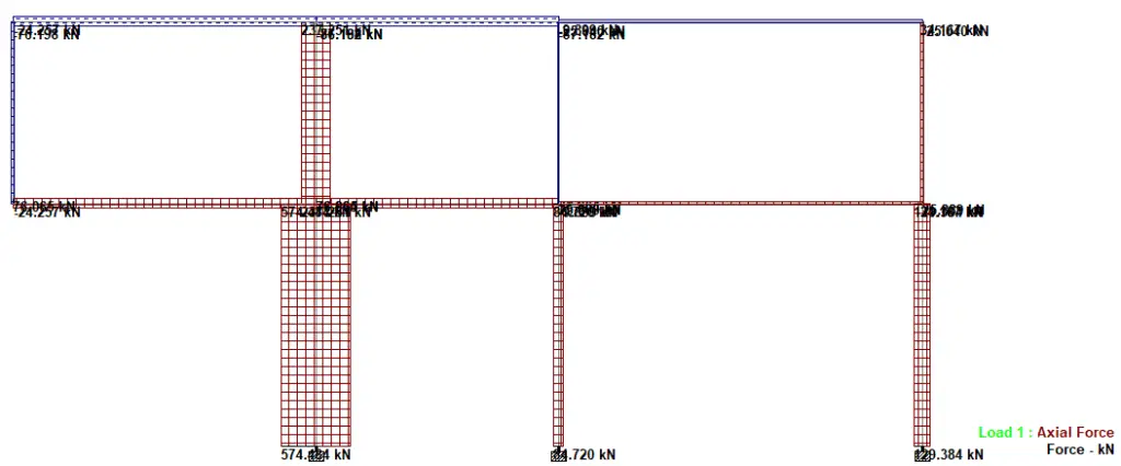
The axial force diagram confirms that the column sitting on top of the cantilever beam is in axial tension, as well as the roof beams.
Analysis Result: With Diagonal column
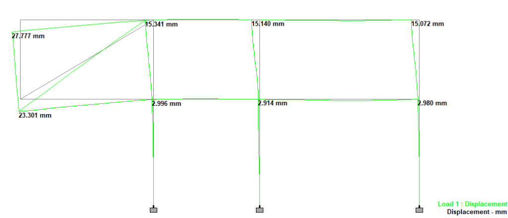
As can be seen in Figure 15, when diagonal columns were introduced, the maximum deflection at the free end of the cantilever reduced to 23.301 mm.
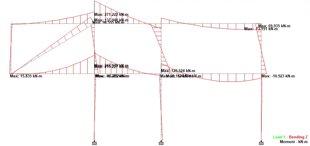
With the presence of the diagonal column, the maximum cantilever moment was 219.221 kNm (see Figure 16). However, the column sitting on top of the cantilever beam reversed to be a compression column, thereby transferring its loads to the cantilever beams.
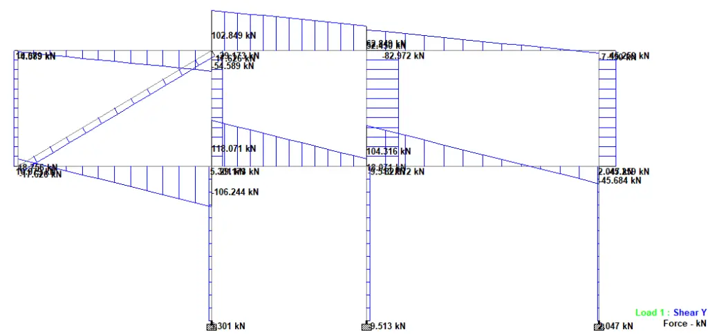
With the presence of diagonal columns, the shear force at the fixed end of the cantilever is reduced to 106.244 kN as shown in Figure 17.
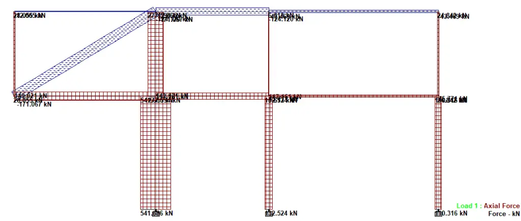
Axial force diagram in Figure 18 shows that the diagonal column is in axial tension.
A table of comparison has been prepared below to show the effect of diagonal tension column support on the deflection behaviour of long span cantilever beams.
| Without diagonal Column | With diagonal column | Percentage decrease | |
| Deflection (mm) | 35.261 mm | 23.301 mm | 33.91% |
| Bending moment (kNm) | 372.701 kNm | 219.221 kNm | 41.18% |
| Shear force (kN) | 158.518 kN | 106.244 kN | 32.97% |
It can therefore be seen that the diagonal tension columns were effective in reducing the deflection, bending moment, and shear force on the cantilever beams. Where architectural specifications permit, cantilever beams and slabs can be supported using diagonal tension members for more structural efficiency.
Source of images:
Instagram @engnivaldo
Architects: @curvoarquitetos








Good one engineer
Excellent work and show of professionalism. We shall contact you when run into trouble during any of our construction projects. Keep it up Engineer.
Good solution by Curvo architects! Can you show us the reinforced steel bars binding diagram of the diagonal cantilever beams?!
Nice work on carrying out the analysis. Now Remove the columns above the cantilever beams and run the analysis again, i am curious to see what happens
Good Solution by the Engineer
I’m curious as to the reason why a tension column was use, what would have been the result should a compression column be used (Basically the column starting from bottom right to top left).
It wouldn’t be a cantilever if that were the case.
Steel tension members would have perhaps been a more efficient design.
Nice solution by then engineer, am curious why didn’t the engineer use the column as compression strut (from the bottom right to top left). Any idea what would be the deflections?
Nice one, I love your explanation
Nice.
Any calculation of long-term effects on reinforced concrete tension beam ?
Nice explanation and concept!
Design is dynamic, however from your explanations, this is not the cheapest method to construct the 5m cantilever beam.
Good work sir. I have learnt a lot from this but how cost effective is it?
This is no longer an issue of cost. Normally, long cantilevers make buildings unnecessarily expensive.
Mirrored orientation of the diagonal member could be selected resulting like a compression brace behaviour. I guess it would be more efficient than a concrete member in tension.