When a structure is acted upon by a force, it undergoes deformation which increases gradually. During the process of deformation, the material of the structure develops some resistance against the deformation. When the material of the structure takes over the influence of the load, the structure becomes stable. The internal resistance which the body develops against the load is referred to as stress. When the configuration of the body cannot resist deformation, it is called a mechanism and no longer a structure.
Types of stresses:
- Direct stress
(a) Tension (b) Compression (c) Shear - Indirect Stress
(a) Bending (b) Torsion - Combined stress
Possible combinations of 1 and 2 above.
Internal Stresses
Let us consider a straight two–force member in tension that is shown in Figure 1 below.
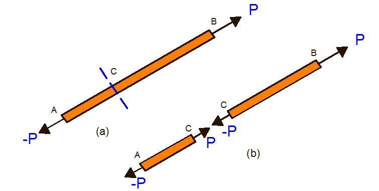
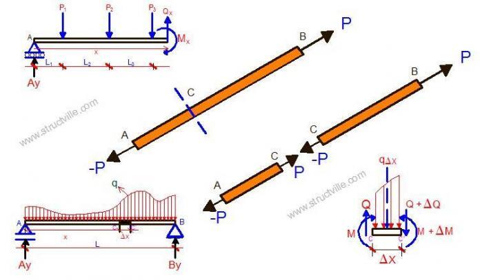
We know that for the member in Figure 1(a) to be at equilibrium, the forces P and –P must be directed along AB in opposite direction and have the same magnitude P. If we cut the member at point C, and if equilibrium must be maintained, we must apply at CA a force P which is equal and opposite to –P, and to CB a force –P which must be equal and opposite to P. Since the member was at equilibrium before the member was cut, internal forces equivalent to these new forces must have existed. This internal force is the axial force in the member.
If we consider the frame that is loaded in Figure 2(a) as shown below;
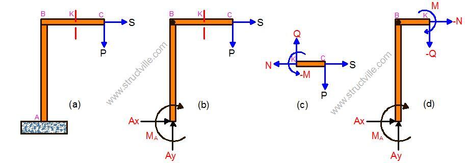
When we cut a section at point K between member BC (Figure 2a) and consider the free body diagram of section KC (Figure 2c), we will realise that for the body to be at equilibrium, the following conditions must be met;
- Application of a force Q at K which is equal and opposite of the force P
- Application of the force N at K which is equal and opposite of the force S
- Application of a moment M at K to balance the moment of P about K
We again, therefore, conclude that the forces must have existed in the member before the section was cut. The force Q is called the shear force, the force N is called the axial force, and moment M is called the bending moment at point K. The knowledge of these internal stresses is so important that in any given structure, we can use it to determine the critical stress in any section, so as to use it to compare with the permissible stress of the material of the structure before failure occurs. It is also necessary when we compute the deformations at any point in the beam, so as to satisfy the requirements for the effective functionality of the structure (serviceability requirements).
Even though real life structural problems are subjected to various and complex systems of loading, the internal forces induced are usually in form of any of the following:
- Shearing forces
- Bending moments
- Axial forces
- Torsion
Shear Forces
When a beam which is in a state equilibrium and subjected to a system of static loading is cut at a section X from the left, it is still expected that the section cut remains at equilibrium, which means that a force must act at the section that is cut. Before the section is cut, this force is provided by the adjacent material in the beam section; hence it acts tangentially to the section from which it is cut.
To ascertain the value of this force, all we need to do is to add up the algebraic value of the forces acting from the left to the point where the section is cut. Internal forces acting tangentially at sections of a beam in equilibrium are known as the shear forces.
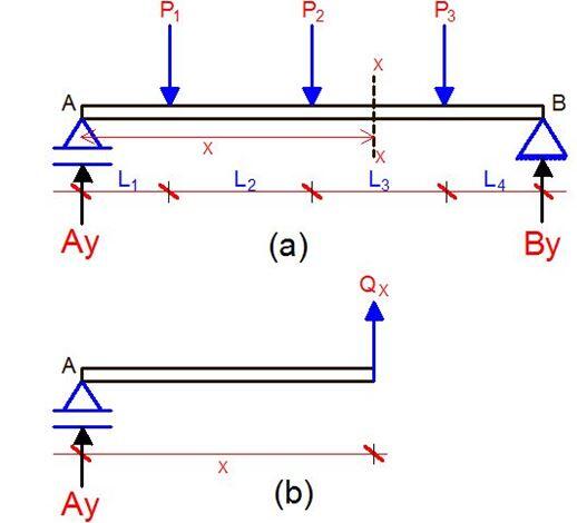
The shear force at section x-x of the beam loaded as shown in figure 3(a) is simply given by the summation of all the vertical forces acting just to the left of the section. In this case, it is denoted by Qx which is the force that balances all the external loads acting to the left of the structure;
Qx is given by;
Qx = Ay – P1 – P2
Bending Moment
Bending moment is defined as the rotational tendency of a force. It is basically given by the force, multiplied by the perpendicular distance. If we still consider the equilibrium at the left of the section we cut from the beam, we will still discover that there will be no resultant moment.
In other words, there will be a moment that will balance the bending moments produced by the other forces if the system is to remain at equilibrium. This is the bending moment of the beam at section X and will have the same value, whether you decide to come from the left or the right of the beam system. Always note that moment is maximum where the value of the shear force is equal to zero.
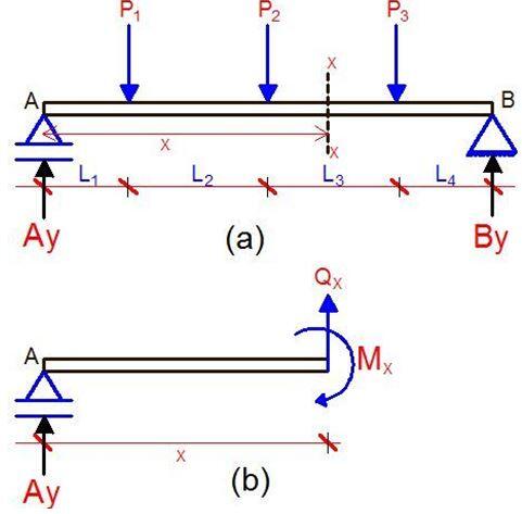
The bending moment is given by the algebraic sum of the moment that is acting just to the left or to the right of the section. Coming from the left of the structure, it is given by;
Mx = (Ay × x) – P1(x – L1) – P2[x – (L1 + L2)]
The value of bending moment in a structure can be negative or positive. When the value of the bending moment is positive, it is said to be a sagging moment and it implies that the beam is in tension in the lower fibre of the material. Otherwise, when it is negative, it is a hogging moment and the tension zone is in the upper fibre of the material (See Figure 5 below).

Axial Forces
Axial loads are loads that are applied along the longitudinal or centroidal axis of the member. These loads are common in trusses, columns, and stanchions, and are sometimes accompanied by some rotation and moment due to the eccentricity of the load or from another external load.
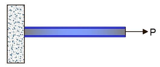
When the load causes extension in the length of the member, it is called a tensile axial force, and when it causes decrement in length, it is a compressive force. The loads on columns and stanchions are usually compressive.
Torsion
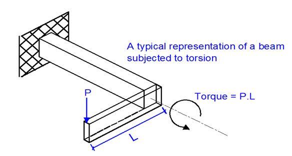
Torsion is very much like a torque that is applied to a beam structure. In other words, torsional stresses produce a kind of twisting effect on the structure. In real-life problems, it is not normally necessary to design for torsion in reinforced concrete structures, since adequate resistance is provided by the nominal shear reinforcements. However, in some structures such as roof gutter or beams supporting canopy slabs, it is necessary to design the beam to resist torsion. In the diagram shown below (Figure 7), the primary beam can be designed to resist torsion T and a point load P.
Relationship between load, bending moment, and shear force
When a beam is subjected to an arbitrary system of loading, its analysis is facilitated if certain relations exist between the applied load, and the internal stresses.
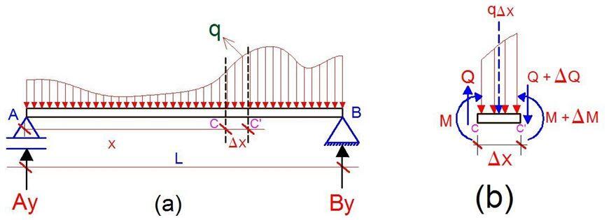
Let us consider a beam AB that is carrying a distributed load as shown in figure 8(a). Let CC’ be two points on the beam at a distance ∆x from each other. The shear force and bending moment at C is denoted by Q and M respectively and at point C’ by Q + ∆Q and M + ∆M. Let us now detach points CC’ and draw the free body diagram as shown in figure 8(b).
Let the summation of the vertical forces be equal to zero.
∑Fy = 0
Then we have; Q – (Q + ∆Q) – q∆x = 0
∆Q = – q∆x; Dividing both sides by ∆x and in the limit allowing ∆x to go to zero, we obtain;
dQ/dx = -q —– (1)
Equation (1) indicates that for a beam loaded as shown in figure 8, the slope of dQ/dx is negative. The equation is valid for only distributed loads, for concentrated loads, the formula is not valid. The absolute value of the gradient at any point is equal to the load per unit length.
Integrating equation (1) between points C and B, we obtain;
QB – QC = -∫q dx —— (2)
This implies that the load between B and C is equal to the area under the load curve between points B and C.
When we consider the sum of the moment for the free body diagram at figure 8(b);
Let the summation of the moment about C’ be equal to zero.
∑Mc’ = 0
(M+ ∆M) – M – (Q∆x ) + q∆x(∆x/2) = 0
∆M = Q∆x – q(∆x)2/2 .
Dividing both sides by ∆x and let ∆x go to zero in the limits;
We obtain;
dM/dx = Q —— (3)
Equation (3) shows that the derivative of the bending moment equation yields the equation for the shear force. This is valid for both when concentrated and distributed load is applied on the beam under consideration.




Very explicit