Manual sketching of flownets is an acceptable way of dealing with two-dimensional groundwater water flow and seepage in soils. However, as the geometry gets more complicated and the flow becomes anisotropic, manual sketching of flownets become more tedious and less accurate. In this case, finite difference solution to flow of water through soils can be adopted.
Many flow problems can be considered as two-dimensional, and in cases where permeability has the same value for all directions, the Laplace’s equation for flow becomes;
(∂2H/∂x2) + (∂2H/∂z2) = 0 ——— (1)
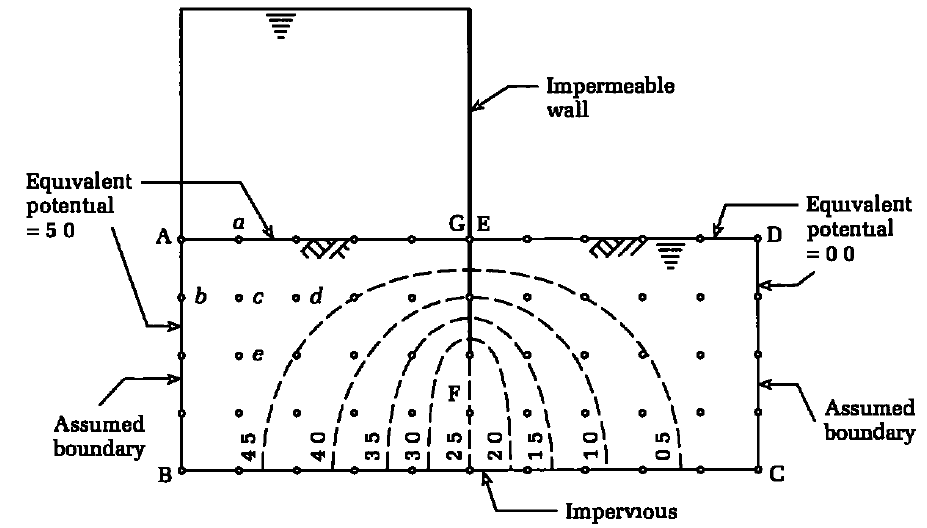
For problems with orthogonal geometry and Laplace’s equation, such as the flow around a pervious barrier shown in Figure 1, the finite difference method provides a quick and accurate solution. This entails replacing the continuous soil cross-section delimited by ABCD with a pattern of discrete points on an orthogonal grid within the cross-section. At each grid point, the governing differential equation can be expressed approximatively in terms of H values at that point and adjacent points.
Previously, we solved the elastic analysis of simply supported thin plates using the finite difference method. We will do the same to solve Laplace’s equation to determine two-dimensional confined flow through soils. Let us consider a grid of a flow domain, as shown in Figure 2, where (i, j) is a nodal point.

Using Taylor’s theorem, we have;
kx(∂2H/∂x2) + kz(∂2H/∂z2) = kx/∆x2 (hi+1,j + hi-1,j – 2hi,j) + kz/∆z2 (hi,j+1 + hi,j-1 – 2hi,j) = 0 ——— (2)
Let α = kx/kz and ∆x = ∆z (i.e., we subdivide the flow domain into a square grid). Then, solving for hi,j from Equation (2) gives;
hi,j = 1/2(1 + α) × (αhi+1,j + αhi-1,j + hi,j+1 + hi,j-1) ——— (3)
For isotropic conditions, α = 1 (kx = kz) and Equation (3) becomes;
hi,j = 1/4 × (hi+1,j + hi-1,j + hi,j+1 + hi,j-1) ——— (4)
Since we are considering confined flow, one or more of the boundaries would be impermeable. Flow cannot cross impermeable boundaries and, therefore, for a horizontal impermeable surface;
∂h/∂x = 0 ——— (5)
The finite difference form of Equation (5) is;
∂h/∂x =1/2∆x(hi,j+1 – hi,j-1) = 0 ——— (6)
Therefore, hi,j+1 = hi,j-1 and, by substitution in Equation (4), we get;
hi,j = 1/4 × (hi+1,j + hi-1,j + 2hi,j-1) ——— (7)
Various types of geometry of impermeable boundaries are encountered in practice, three of which are shown in Figure 3. For Figure 3a, b, the finite difference equation is;
hi,j = 1/2 × (hi+1,j + hi,j-1) ——— (8)

and, for Figure 3c,
hi,j = 1/3 × (hi,j-1 + hi+1,j + hi,j+1 + 0.5hi-1,j + 0.5hi,j+1) ——— (9)
The pore water pressure at any node (ui,j) is;
ui,j = γw(hi,j – zi,j) ——— (10)
where zi,j is the elevation head.
Contours of potential heads can be drawn from discrete values of hi,j. The finite difference equations for flow lines are analogous to the potential lines; that is, ψs replaces h in the above equations and the boundary conditions are specified for ψs rather than for h.
The horizontal velocity of flow at any node (vi,j) is given by Darcy’s law:
vi,j = kxii,j ——— (11)
Where ii,j is the hydraulic gradient expressed as;
ii,j = (hi+1,j – hi-1,j)/2∆x ——— (12)
Therefore;
vi,j = kx/2∆x × (hi+1,j – hi-1,j) ——— (13)
The flow rate, q, is obtained by considering a vertical plane across the flow domain. Let L be the top row and K be the bottom row of a vertical plane defined by column i (Figure 2). Then the expression for q is;
q = kx/4[hi+1,L – hi-1,L + 2∑(hi+1,j – hi-1,j) + hi+1,K – hi-1,K] ——— (14)
Procedure of Finite Difference Solution to Flow of Water Through Soils
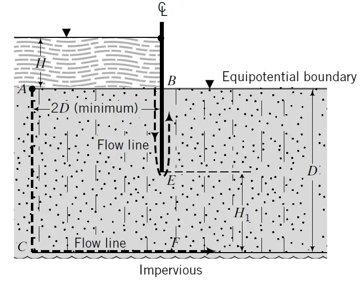
The procedure to determine the distribution of potential head, flow, and porewater pressure using the finite difference method is as follows (Budhu, 2011):
- Divide the flow domain into a square grid. Remember that finer grids give more accurate solutions than coarser grids, but are more tedious to construct and require more computational time. If the problem is symmetrical, you only need to consider one-half of the flow domain.
For example, the sheet pile wall shown in Figure 4 is symmetrical about the wall and only the left half may be considered. The total flow domain should have a width of at least four times the thickness of the soil layer. For example, if D is the thickness of the soil layer (Figure 4), then the minimum width of the left half of the flow domain is 2D. - Identify boundary conditions, for example, impermeable boundaries (flow lines) and permeable boundaries (equipotential lines).
- Determine the heads at the permeable or equipotential boundaries. For example, the head along the equipotential boundary AB (Figure 4) is DH. Therefore, all the nodes along this boundary will have a constant head of DH. Because of symmetry, the head along nodes directly under the sheet pile wall (EF) is DH/2.
- Apply the known heads to corresponding nodes and assume reasonable initial values for the interior nodes. You can use linear interpolation for the potential heads of the interior nodes.
- Apply Equation (4), if the soil is isotropic, to each node except (a) at impermeable boundaries, where you should use Equation (7), (b) at corners, where you should use Equations (8) and (9) for the corners shown in Figure 3a–c, and (c) at nodes where the heads are known.
- Repeat item 5 until the new value at a node differs from the old value by a small numerical tolerance, for example, 0.001 m.
- Arbitrarily select a sequential set of nodes along a column of nodes and calculate the flow, q, using Equation (14). It is best to calculate q’ = q for a unit permeability value to avoid too many decimal points in the calculations.
- Repeat items 1 to 6 to find the flow distribution by replacing heads by flow q’. For example, the flow rate calculated in item 7 is applied to all nodes along AC and CF (Figure 4). The flow rate at nodes along BE is zero.
- Calculate the porewater pressure distribution by using Equation (10).
References
[1] Budhu M. (2011): Soil Mechanics and Foundations (3rd Edition). Pearson Education
[2] Tomlinson M. J. (2001): Foundation Design and Construction (7th Edition). John Wiley and Sons, Inc




Can you confirm that equation 9 is correct, I think there might be an extraneous h_i,j+1 term.
Thanks for sharing this insightful information