Inclined or slanted columns are columns that are leaning at an angle away from perfect verticality (90 degrees to the horizontal). This is usually intentional and not due to imperfection from materials or construction. The degree of inclination can vary depending on the designer’s intentions. In this article, we are going to review the analysis and design of inclined columns using standard design codes.
Inclined columns can be introduced into a building to serve architectural or structural functions. The design of an inclined column is like the design of any other column but with special attention paid to the changes in stresses due to the eccentricity of the axial load on the column. In some cases, inclined columns can be more susceptible to second-order effects than perfectly vertical columns.

When a column in a structure is perfectly straight, first-order bending moment and other internal stresses are induced due to the externally applied loads. However, when a column is inclined at an angle to the beams or floor that it is supporting, changes in bending moments are observed due to the eccentricity of the axial load with respect to the longitudinal axis column. Such effects can be investigated for pinned supports or fixed supports.
In the design of inclined columns (say in reinforced concrete or steel), it is usually very sufficient to analyse the structure and obtain the design internal forces (bending moment, shear, and axial force) using first-order linear analysis. However, when required, the analysis can be extended to second-order non-linear analysis to account for secondary effects which may affect the stability of the column.
To verify the effect of inclination on the design of columns, let us investigate the following cases of a column with a fixed base in reinforced-concrete construction.
Dimensions of beam = 600 x 300 mm
Dimensiond of column = 300 x 300 mm
Ultimate load (factored load) on the beam = 70 kN/m
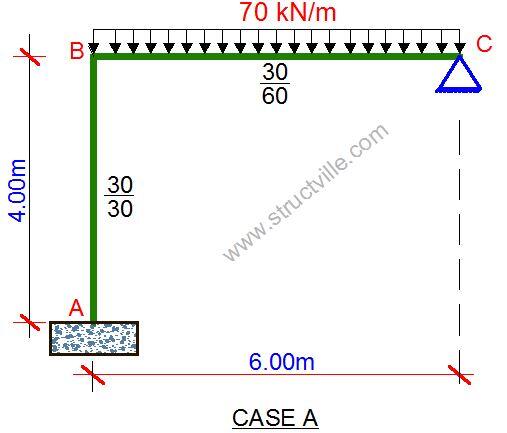
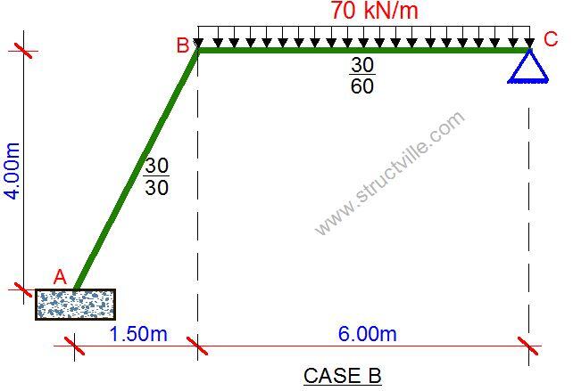
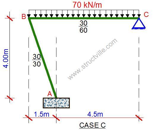
When the frames were analysed using first-order linear analysis, the following results were obtained;
CASE A

Maximum column design axial force = 220.219 kN
Column design shear force = 22.880 kN
Column design moment = 61.313 kNm
CASE B

Maximum column design axial force = 241.712 kN
Column design shear force = 19.608 kN
Column design moment = 56.624 kNm
CASE C

Maximum column design axial force = 226.991 kN
Column design shear force = 20.892 kN
Column design moment = 59.247 kNm
From the analysis results, it could be seen that case A gave the highest column moment but the least axial force, while case B gave the lowest column design moment but highest column axial force. The design of the column can then be carried out for each of the cases presented.








?
An inclined rc column stirrups will have to be at a lesser distance in relation to a vertical one , because it is more inclined to bend.
it’s a good knowledge. but is there a possibility using inclined coloumn to the zone that have big ratio of earthquake?
Great
Detailing of the columns should also be explained for new practicing engineers
can you provide a calculation for the case C.