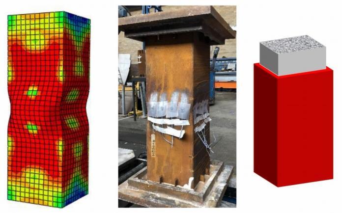
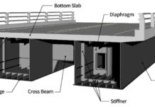
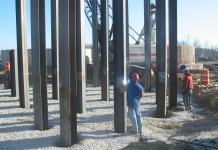
In terms of structural performance and constructability, concrete-filled steel tubular (CFST) members provide a number of advantages over bare steel or reinforced concrete elements. These advantages have led to a wider range of practical applications, such as increased strength and ductility of the core concrete due to the steel tube’s confining effect, increased resistance to local buckling of the steel tube due to the core concrete’s restriction of inward deformations, improved fire resistance of CFST members due to the concrete’s heat sink effect, and improved constructability due to the steel tube acting as formwork during the concrete pouring.
Torsion occurs in structural members as a result of twisting due to an applied torque. CFST beams with curved on-plan surfaces, CFST corner columns of structures that twist under wind or earthquake loads, and I-beams with CFST compression flanges that experience lateral torsional buckling are common instances where such actions might occur in CFST members.
Furthermore, because the stiffness centre and the mass centre of these structures do not lie in the same location, in reality, the piers of curved bridges, skew bridges, and complicated building structures are always exposed to torsion under horizontal earthquake action.
It is well known that the shape of the cross-section affects the confinement effect in CFST members and that square CFST columns typically possess somewhat lower strength and ductility than similar circular CFST columns. Square CFST columns, however, are frequently used for practical reasons, such as more elaborate beam-to-column connections.
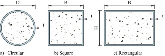
Numerous researchers have conducted experimental and numerical studies on the behaviour of square CFST members under various loading conditions. These include a number of tests on square CFST beam-columns that were loaded under pure compression to bending. Additionally, experimental tests have been conducted on square CFST beam-columns utilizing high-strength steel sections with yield strengths up to 750 MPa, along with computational calculations. Interaction formulae for design purposes have been developed on the basis of the findings.
A paper on the torsional rigidity of CFST square columns was recently published in the journal Structures (Elsevier) by researchers from the Department of Civil and Environmental Engineering at Imperial College London in London, the School of Civil and Architecture Engineering at Northeast Petroleum University in Daqing, China, and the School of Civil Engineering & Architecture at Nanjing Institute of Technology in Nanjing, China.
According to the authors, available literature makes it obvious that while there have been several examinations into the structural response of square CFST sections in compression and bending, there has been less research into the torsional performance of square CFST sections.
To address the knowledge gap, the authors used the concept of minimum strain energy to develop an analytical equation for the uniform torsional rigidity of square CFST sections. Since it is generally known that uniform torsional stiffness prevails over non-uniform (warping) torsional rigidity in the case of closed sections, emphasis is made on the uniform torsional rigidity of square CFST sections.
The accuracy of the obtained formula was then evaluated using current theoretical findings, test data, and the finite element simulations carried out in the study. Finally, the significance of the theoretical formulation’s constituent parts is examined, and a simplified design formula was provided.
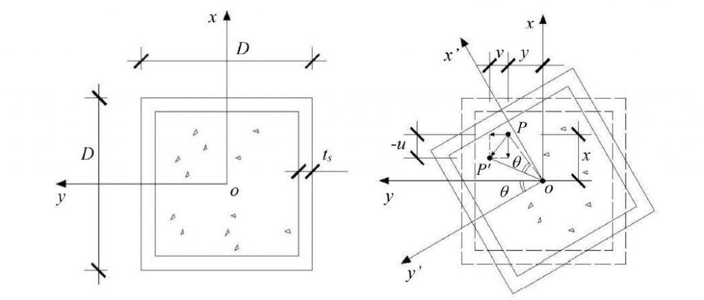
Basic Assumptions in the Determination of Torsional Rigidity
When determining the torsional rigidity of square CFST sections, the following fundamental presumptions are made:
(1) Every point in the cross-section rotates via the angle θ(z) about the centre of twist because the square CFST members’ cross-sections do not deform in-plane when they are twisted. The stiff peripheral assumption of thin-walled bars made by Vlasov is analogous to this one. This assumption allows for the determination of the transverse deformations at any location on the cross-section of square CFST members.
(2) During uniform torsion of the square CFST members, there is no longitudinal slip at the interface between the core concrete and the steel tube, i.e., the longitudinal warping of the steel and concrete are compatible at the interface.
(3) Pure torque is applied to the square CFST component, which results in no restrictions on any variations in the longitudinal warping and does not vary along the length of the member.
The notations used in the study are as follows:
Es, Gs, and μs are the steel cross-modulus sections of elasticity, shear modulus, and Poisson’s ratio, whereas Ec, Gc, and μc are the filled concrete’s modulus of elasticity, shear modulus, and Poisson’s ratio. The section depth and wall thickness of the steel tube are designated by D and t, respectively, while the length of the square CFST member is denoted by L.
Torsional deformation occurs when a member is subjected to a torsional moment (T), where θ(z) is the angle at which the cross-section is twisted. For a member of length L, the angle of twist at the tip, or tip rotation, is given by:
θL = TL/(GJ)k ——— (1)
where (GJ)k is the torsional rigidity of CFST cross-sections, considering the contributions of both the concrete core and the steel tube, to be determined in this study.
Theoretical Formulations
In the study, the strain energy of the concrete core and the steel tube was determined as;
U = ½(GJ)k,SEϕ2L ——– (2)
where (GJ)k,SE is the uniform torsional rigidity derived from the principle of minimum strain energy of a square CFST cross-section, which can be expressed as follows:
(GJ)k,SE = 0.1407D4GcΨ(m, α) ——– (3)
Where;
Ψ is the non-dimensional constant of uniform torsional rigidity of square CFST sections, m = Gs/Gc is the ratio of the shear modulus of steel to that of concrete, α = As/Ac, referred to as the steel ratio, is the ratio of the cross-sectional area of the steel As to the cross-sectional area of the concrete Ac, and can be approximated as α ≈ 4t/D.
When the steel ratio α = 0, the equation (3) reduces to the uniform torsional rigidity of a square section of a single material (pure concrete), i.e.
(GJ)k,SE ≈ 0.1407D4Gc ——– (4)
The exact solution, as given by Timoshenko and Goodier (1970), is:
(GJ)k,TG = 0.1406D4Gc ——– (5)
It can be seen that the difference between the analytical solution and the exact solution is only 0.1%. This shows that the longitudinal displacement mode assumed in the paper is reasonable, and that the principle of minimum strain energy has been suitably applied.
Experimentation Verification
The outcomes of a torsion test performed by prior researchers on a square CFST member were taken into consideration in order to further confirm the accuracy of the derived uniform torsional rigidity. The tested member’s geometrical and material characteristics are shown in the Table below where fy is the steel’s yield strength, fcu and fck are concrete’s cube and cylinder strengths.
| Property | Chen (2003) | Kitada and Nakai (1991) |
| Length L (mm) | 1620 | 1590 |
| Depth D (mm) | 200 | 123.5 |
| Thickness t (mm) | 4.5 | 4.5 |
| fy (MPa) | 261.4 | 274 |
| fcu (MPa) | 39.0 | 25.6 |
| fck (MPa) | 26.1 | 17.2 |
| Es (GPa) | 206 | 206 |
| Ec (GPa) | 32.4 | 28.1 |
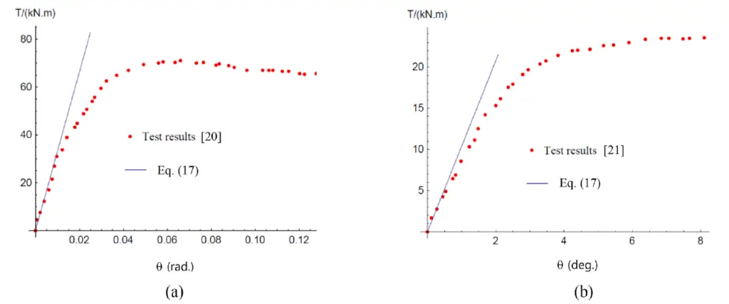
The calculated rigidity of the member, as determined from Eq. (3), is also plotted in Fig. 3(a) (with G = E/[2(1 + μ)] and μc = 0.2 for concrete and μs = 0.3 for steel) and can be seen to be in good agreement with the test result in the elastic range (i.e. up to about T = 40 kNm for the case shown). Similarly, good predictions of torsional rigidity (within about 12%) were achieved following comparisons with the experimental results reported in (Kitada and Nakai, 1991), as shown in Fig. 3(b), the key properties of which are provided in Table 1 above.
Finite Element Verification
Additionally, the authors used finite element modelling to confirm the derived uniform torsional rigidity found in Eq. (3). Using SOLID65 and SHELL181 elements, respectively, for the core concrete and steel tube and concrete, a series of square CFST members were modelled in ANSYS software. Following a convergence study, an element size of 20 mm in all directions was chosen. To model the contact between the steel and the concrete, the contact elements TAGRE170 and CONTAL173 were employed.
At the tips of the members, a MASS21 mass element with rotational degrees of freedom was introduced to add torque, and all node degrees of freedom were constrained at the fixed ends of the members.
Twelve square CFST members with varying lengths and depths were modelled. Each member was made of a Q235 steel SHS outer tube (Es = 206 GPa and μs = 0.3) and a C40 concrete core (Ec = 32.4 GPa and μc = 0.2). Tip rotations were calculated using two methods:
(1) the FE models, which provided θL,FE; and
(2) Eq. (3), which combined the uniform torsional rigidity (GJ)k provided by Eq. (3) to provide θL,SE (referred to as the “Theory”).
The results, along with the forecasts’ mean and standard deviation, are given in the Table below. The results show that the theoretical tip rotations and the finite element tip rotations correspond quite closely, with the largest absolute difference being less than 0.5%.

Statistical Sensitivity
The uniform torsional stiffness of a square CFST section and the sensitivity of the non-dimensional parameter to variations in the steel ratio and the ratio of the shear modulus of steel to that of concrete were also taken into consideration in the study. For a value of Es = 210 GPa and μs = 0.3, the shear modulus of steel is given by Gs = Es/[2(1 + μs)], which corresponds to a value of Gs ≈ 81 GPa. Depending on the concrete grade, the shear modulus of concrete Gc typically ranges from 12.5 GPa to 15.8 GPa. As a result, m virtually solely affects the grade of concrete, and its value falls between 5.1 and 6.4.
The relationship between Ψ and m for various steel ratios was displayed on a graph, and the following was noted:
(1) As α changes, the trend of the Ψ -m relationship remains similar, indicating that the relationship between Ψ and α is approximately linear
(2) As m increases, Ψ decreases.
The Ψ -α relationship for different values of m showed that:
(1) As m changes, the trend of the Ψ -α relationship also remains similar indicating that the relationship between Ψ and m is approximately linear
(2) As α increases, Ψ also increases.
Overall, it may be concluded that Ψ varies approximately linearly with both α and m, and that the influence of the steel ratio α is more significant.
Simplified Design Formula
The principle of superposition may be used now that it has been established that the relationships between ψ and both m and α are roughly linear. Consequently, the uniform torsional rigidity of a square CFST section can also be written as:
(GJ)ksup =(GJ)s +(GJ)c

where the first term is the torsional rigidity of a thin-walled square steel tube (GJ)s, and the second term is the torsional rigidity of a solid square concrete core (GJ)c.
The following results were reached after studying the uniform torsional rigidity of square concrete-filled steel tubular (CFST) sections:
- It has been established that an analytical formula for determining the uniform torsional rigidity of square CFST sections yields highly precise predictions of the numerical data (within 0.5%). The findings of earlier experiments were accurately predicted as well.
- It has been demonstrated that the uniform torsional stiffness varies roughly linearly with both the steel ratio and the ratio of the shear modulus of steel to concrete, with the steel ratio being more significant.
- Continuing from (2), the uniform torsional rigidity of square CFST cross-sections has been satisfactorily simplified by the principle of superposition.
- By combining the data provided here with those of previous researchers, a very accurate predictive model for the full range elastic-plastic torsion moment-deformation response of CFST members may be created.
- The work that has been described can be expanded to examine the uniform torsional rigidity of CFST components with different cross-sectional forms.
Article Credit:
Zhang W. F., Gardner L., Wadee M.A., Chen K.S., Zhao W.Y. (2022): On the uniform torsional rigidity of square concrete-filled steel tubular (CFST) sections. Structures 43 (2022) 249–256. https://doi.org/10.1016/j.istruc.2022.06.046
The contents of the cited original article published by Cement and Concrete Research (Elsevier) is open access, under the CC BY license (http://creativecommons.org/licenses/by/4.0/) which allows you to share and adapt (remix) the article provided the appropriate credit is given, and the link to this license provided.
References
[1] Chen Y.W. (2003): Research on torsion and section behaviour of concrete-filled steel tubular columns. Taiwan Central University, 2003.
[2] Kitada T, Nakai H. (1991): Experimental study on the ultimate strength of concrete-filled square steel short members subjected to compression or torsion. Proceedings of the Third International Conference on Steel Concrete Composite Structures. Fukuoka, Japan, 1991.
[3] Timoshenko SP, Goodier JN. (1970): Theory of Elasticity. 3rd Edition, 1970, McGraw-Hill, New York.
[4] Zhang W. F., Gardner L., Wadee M.A., Chen K.S., Zhao W.Y. (2022): On the uniform torsional rigidity of square concrete-filled steel tubular (CFST) sections. Structures 43 (2022) 249–256. https://doi.org/10.1016/j.istruc.2022.06.046

