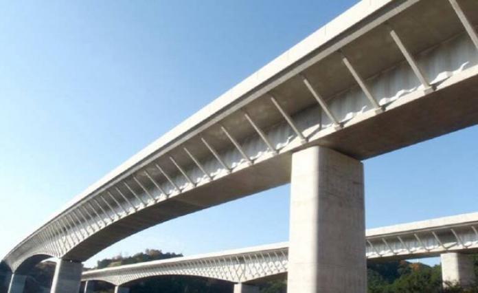
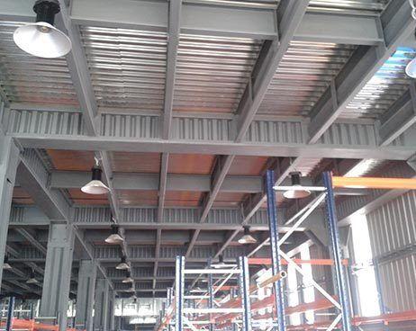
Corrugated web girders are being utilized more commonly in structural engineering due to their many beneficial qualities, such as lower dead load, increased shear buckling strength, and a special structural behavior known as “accordion effect.” Because of this, designing girders is simpler than it would be for those with flat web.
For the design of these girders, the stability of the local and global members is essential. The effect of local stability on cross-sectional resistances, specifically the bending moment resistance, shear buckling resistance, and resistance against transverse force, has been well studied in the past. These resistances can now be calculated using precise design models.
According to Jager et al (2022), several research works have shown that girders with corrugated web have a higher elastic critical moment than those with flat web. This implies that the lateral-torsional buckling strength of beams increases when the web is corrugated.
However, the increment has been viewed in several ways by being associated with the cross-sectional characteristics. The majority of studies concur that the web contribution should not be taken into account when calculating inertias about the strong and weak axis, although there are discrepancies when taking the enhanced elastic critical moment into account.
The elastic critical moment of a conventional flat web girder subjected to uniform bending moment can be calculated by Eq. (1) according to EN1993-1-1 as;
Mcr = π/kL √EIz [(π/kwL)2 EIw + GIt] ——– (1)
Where L is the span of the girder, E is the elastic modulus, G is the shear modulus, Iz is the moment of inertia about the minor axis, It is the torsional constant, Iw is the warping constant, k is the effective length factor about the weak axis rotation and kw is the effective length factor with respect to warping.
To account for the critical elastic moment of corrugated web girders, previous research work by Lindner (1990) suggested an additional term with a correction factor cw in the warping constant given by Eqs. 2–4 for double symmetric sections in order to consider the greater performance (c1 = 8, c2 = 25); where Iw,flat is the warping constant of flat web girder.
Iw = Iw,flat + cw (L2/Eπ2) ——– (2)
cw = a32 (hw + tf)2/[c1⋅ux⋅(a1 + a4) ——– (3)
ux = (hw + tf)/2⋅G⋅a1⋅tw + (hw + tf)2⋅(a1 + a4)3/c2⋅a12⋅E⋅bf ⋅tf3 ——– (4)
Larsson and Persson (2013) performed a notable FE study and found that the proposal of Lindner (1990) gives the best approximation to the numerical results. However, this additional term depends on the girder length which is not possible for a sectional constant. Therefore, they substituted the Lindner’s proposal into Eq. (1) in order to rearrange the additional term to the torsional constant according to Eq. (5).
It = It,flat + cw/G ——– (5)
The appropriateness of Eq. (5) was confirmed by Lopes et al. (2017) and they proposed a slightly modified correction factor cw for trapezoidally and sinusoidally corrugated web girders (c1 = 22, c2 = 300 in Eqs. 3–4) based on FE analysis.
According to EN1993-1-1 [2] the reduction factor (χLT) for the lateral-torsional buckling strength for rolled sections or equivalent welded sections with flat web may be calculated by Eqs. 6–8, where αLT is the imperfection factor (for different buckling curves: a – 0.21, b – 0.34, c – 0.49, d – 0.76), λLT is the relative slenderness, β is the multiplication factor and λLT,0 is the relative slenderness limit. The standard suggests to use buckling curve d if the depth-to-width ratio of the section is greater than 2; otherwise the buckling curve c shall be used. In Eq. (6) My is the cross-sectional bending moment resistance considering the local flange buckling.
λLT = √[My/Mcr] ——– (6)
λLT,0 = 0.4, and β = 0.75
ϕLT = 0.5[1+ αLT (λLT – λLT,0) + βλLT2] ——– (7)
χLT = 1/[ϕLT + √(ϕLT2 – βλLT2)] but χ ≤ 1.0 ——– (8)
In the past, nonlinear FE (finite element) analysis was mostly used to explore the ultimate lateral-torsional buckling strength; hence, there aren’t many test data available. Only a small number of experimental tests and some non-linear FE analysis performed by various researchers have been used to study the ultimate lateral-torsional buckling strength of corrugated web girders.
Researchers (Jager et al, 2022) from the Department of Structural Engineering at Budapest University of Technology and Economics, Hungary, recently worked on an experimental study using 11 large-scale test specimens to examine the lateral torsional buckling resistance of corrugated web girders.
The study was published in the journal, Structures (Elsevier). In the research work, the prior design recommendations for trapezoidal corrugated web girders’ lateral-torsional buckling strength were compared and evaluated based on the test results, and a preliminary design buckling curve was provided.
Test Setup and Experimental Study
11 large-scale test specimens were examined under four-point-bending condition as part of the research program by Jager et al (2022). Investigations were conducted on six distinct girder geometries with the same trapezoidal corrugation profile but varied flange sizes. Five more specimens were employed in test replications to check the accuracy of the findings. The widths of the parallel and inclined web folds are the same for all specimens (a1 = a2 = 98 mm), as they are often employed in bridges with a corrugation angle of 45°.
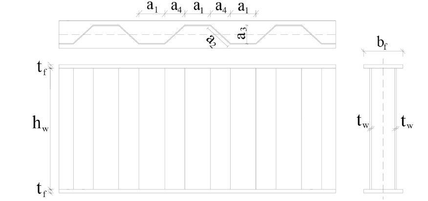
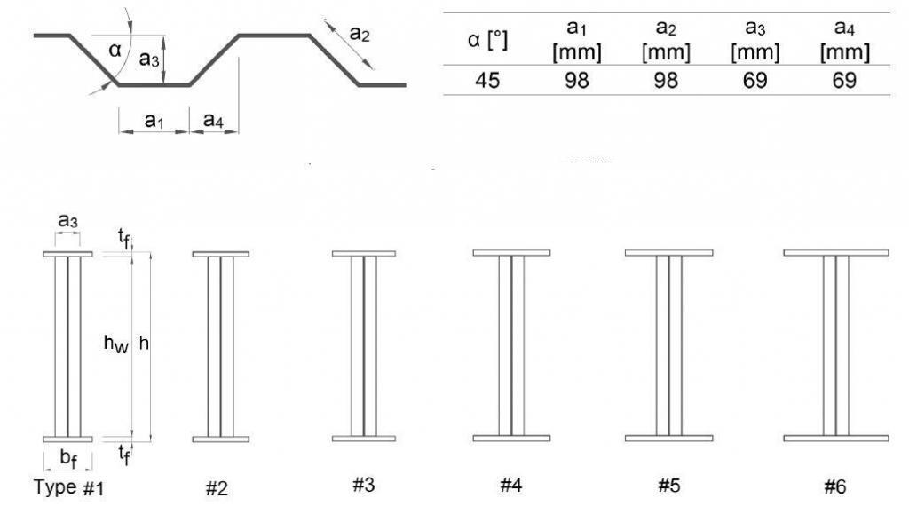
The six specimen types with varying flange sizes were depicted in scaled drawings as shown above, and the girder numbers were assigned in accordance with the rising flange diameters. The nominal flange thickness (tf) of specimen types #1, #2, and #3 is 14 mm, whereas specimen types #4, #5, and #6 have a 16 mm flange thickness. There are five different nominal flange widths (bf): 140, 160, 180, 220, 250, and 300 mm.
With a nominal web depth (hw) of 520 mm, all specimens have a web thickness (tw) of 6 mm. Vertical stiffeners with a nominal thickness (ts) of 10 to 16 mm were installed at the load introduction and support positions. To analyze the lateral-torsional buckling behavior of corrugated web girders, a wide range of varied LTB slenderness ratios were covered by the specimens.
S355 steel grade was used for the flanges, while S235 steel grade was used for the web, with nominal yield strengths of 355 MPa and 235 MPa, respectively. Coupon tests in accordance with ISO6892-1 were used to assess the material’s characteristics.
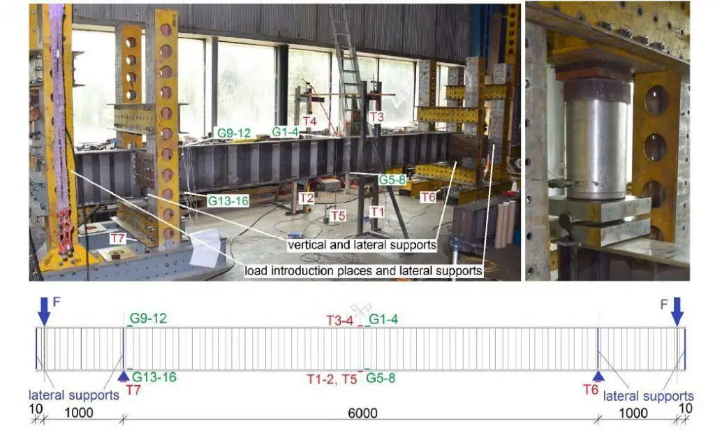
Prior to testing, the rigid frame measuring system’s spatial coordinates were calculated using geodetic triangulation from three places using a total station theodolite to achieve high precision. Each specimen was subjected to a static load of around 0.1 kN/s]. To assess the elastic response of the structure and the stiffness of the investigated girders in the elastic domain, loops were run five times by equal loading steps during the loading and unloading process until achieving about 60% of the projected ultimate load bearing capacity.
The hydraulic jacks that were being used were coordinated and attached to the same hydraulic system. In order to assess the results and compare them using FE models, the test specimens’ observed load-displacement curves, buckling forms, and ultimate failure modes were documented on photos. Displacement control was used during the experiments, and the post-buckling ranges were also investigated. Following the testing, portions of steel plate were removed from the intact flange and web parts of each specimen for material testing.
Overall Results and Failure Modes
According to the findings of the study, girders with compact flanges experienced pure lateral-torsional buckling failure, whereas girders with slender flanges experienced flange buckling failure in conjunction with lateral-torsional buckling failure. Furthermore, because of the rigid cross-sectional movement failure modes, no distortional web failure developed.
Moreover, it was observed that after unloading, slender specimens can regain proportionately bigger displacements owing to elastic buckling, while heavier flanged samples can experience inelastic buckling. The study also showed that initial imperfections have significant resistance reduction effect on the lateral-torsional buckling strength.
Comparison with Design Proposals
The authors compared the lateral-torsional buckling curves of EN 1993-1-1 (β =0.75) to various reduction factors estimated from the test findings (χLT,test). By the calculation of the relative slenderness three different proposals for the elastic critical moment are used:
(i) without any modification in the torsional or warping constants,
(ii) with an additional term in the torsional constant proposed by Larsson and Persson (2013) using the correction factor of Lindner (1990) presented by Eq. (5), and
(iii) with the slightly modified correction factor of Lindner according to Lopes et al. (2017).
The web’s contribution to the moment of inertias surrounding the strong and weak axes was ignored in every case. Both effective length factors (kw and k) were arbitrarily set to 0.5 in order to optimize the elastic critical moment and offer a safe side solution for the buckling curve because the test specimens were almost completely constrained against warping and rotation about the weak axis. It should be noted that all test results were above the previous proposal’s buckling curve band.
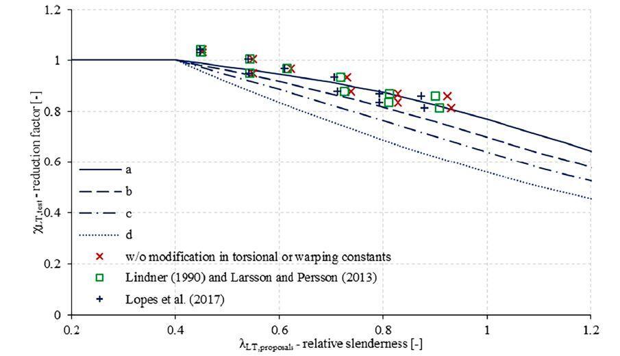
The calculation methods considered in the study are in harmony with the “accordion effect” of corrugated web girders. It is to be noted all test results are above the buckling curve b and the proposal of Lopes et al. (2017) gives the larger elastic critical moment and smaller relative slenderness then Larsson and Persson’s (2013) solution.
The calculated resistances are determined according to the equation below;
Mb,R = χLT⋅My ——– (9)
Where the reduction factors (χLT) are obtained from Eqs. 6–8 using the above mentioned three different proposals for the elastic critical moment. It can be seen that the best fit and safe side solution is provided by the proposal of Lopes et al. (2017) using buckling curve b.
By comparing the test and computed lateral-torsional buckling resistances, The authors pointed out that the Lopes et al (2017) proposal’s suggestion offered the greatest match and safest approach to take. However, it should be highlighted that a more extensive statistical evaluation should be carried out in accordance with EN 1990 AnnexD, expanded by advanced FE analysis, in order to determine an applicable buckling curve that satisfies the safety criterion of the Eurocode.
Article Credit:
B. Jager, L. Dunai, B. Kovesdi (2022): Lateral-torsional buckling strength of corrugated web girders – Experimental study. Structures 43 (2022) 1275–1290 https://doi.org/10.1016/j.istruc.2022.07.053
The contents of the cited original article published by Cement and Concrete Research (Elsevier) is open access, under the CC BY license (http://creativecommons.org/licenses/by/4.0/) which allows you to share and adapt (remix) the article provided the appropriate credit is given, and the link to this license provided.
References
[1] Larsson M, Persson J, Lateral-torsional buckling of steel girders with trapezoidally corrugated webs, MSc thesis, Gothenburg, Sweden, 57, 2013.
[2] Lindner J. Lateral torsional buckling of beams with trapezoidally corrugated webs, Proceedings of the 4th International Colloquium on Stability of Steel Structures, Budapest, Hungary, 79-82, 1990.
[3] Lopes GC, Couto C, Real PV, Lopes N. Elastic critical moment of beams with sinusoidally corrugated webs. J Constr Steel Res 2017;129:185–94.

