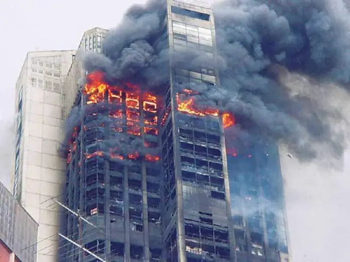
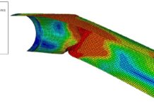
At normal temperatures, structural design requires the structure to support the design ultimate loads (the ultimate limit state) while also limiting deformation and vibrations under serviceability circumstances (the serviceability limit state). The fire resistance design of steel columns and beams is aimed at maintaining the structural integrity of the structure at elevated fire temperature within a stipulated time. At room temperature, the structure’s design effort is primarily focused on preventing excessive deformations.
The basic goal of fire-resistant design is to prevent collapse before the stated fire resistance duration expires. During a fire, large deformations are normal and do not need to be calculated in the fire design. For a particular fire loading, the load-bearing function of a steel member is assumed to be lost at time t, when:
Efi,d = Rfi,d,t ——– (1)
where;
Efi,d is the design value of the relevant effects of actions in the fire situation;
Rfi,d,t is the design value of the resistance of the member in the fire situation at time t.
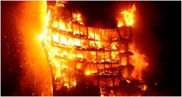
Rfi,d,t represents the design resistance of a member in a fire situation at time t, which can be Mfi,t,Rd (design bending moment resistance in a fire situation), Nfi,t,Rd (design axial resistance in a fire situation), or any other force (separately or in combination), and the corresponding values of Mfi,Ed (design bending moment in a fire situation), Nfi,Ed (design axial force in the fire situation), etc. represent Efi,d.
The design resistance Rfi,d,t at time t shall be determined by reducing the design resistance for normal temperature design according to EN 1993-1-1 to account for the mechanical properties of steel at elevated temperatures (assuming a consistent temperature across the cross section). The differences in the equations for cold and fire design are mostly related to the shape of the stress-strain diagram at ambient temperature and the shape of the diagram at elevated temperature. Figure 2 shows this schematically.

When employed at greater temperatures, some adaptation to the design equations established for room temperature circumstances is required. If a non-uniform temperature distribution is employed, the normal temperature design resistance to EN 1993-1-1 should be changed based on this temperature distribution.
Fire Resistance Design of Steel Columns
The most important design requirements of steel structures is the verification of the buckling and shear resistance of the column. For uniaxial or biaxial bending of steel columns, the interaction factors should be duly considered.
Buckling Resistance
The design value of the compression force in the fire situation, Nb,fi,Ed, at each cross section should satisfy the following condition:
Nb,fi,Ed/Nb,fi,t ,Rd ≤ 1.0 ——– (2)
where the design buckling resistance Nb,fi,t,Rd at time t of a compression member with a Class 1, Class 2 or Class 3 cross section with a uniform temperature θa should be determined from:
Nb,fi,t ,Rd = χfiAky,θfy / γM,fi ——– (3a)
and for Class 4 cross sections
Nb,fi,t ,Rd = χfiAeff k0.2p,θ fy /γM,fi ——– (3b)
where;
ky,θ is the reduction factor for the yield strength of steel at uniform temperature θa ,reached at time t.
k0.2p,θ is the reduction factor for the 0.2% proof strength of steel at uniform temperature θa, reached at time t,.
Aeff is the effective area of the cross section when subjected only to uniform compression;
χfi is the reduction factor for flexural buckling in the fire design situation, given by Eq. (5.45).
The value of χfi should be taken as the lower of the values of χy,fi and χz,fi determined according to:
χfi = 1/[φθ + φθ2 −λθ2] ——– (4)
where;
φθ = 0.5[1 + αλθ + λθ2] ——– (5)
and the imperfection factor, α , proposed by Franssen et al (2005) is given by;
α = 0.65 √235/fy ——– (6)
The non-dimensional slenderness λθ for the temperature θa, is given, for Class 1, 2 and 3 by;
λθ = λ √(ky,θ/kE,θ) ——– (7a)
and for Class 4 cross sections
λθ = λ √k0.2 p,θ/ kE,θ) ——– (7b)
where;
λ is the non-dimensional slenderness at room temperature given by Eq. (8a) or Eq. (8b) using the buckling length in fire situation lfi . The non-dimensional slenderness at room temperature, λ, is given by;
λ = √(Afy/Ncr) ——– (8a)
for Class 1, 2 and 3 cross sections or;
λ = √(Aefffy/Ncr) ——– (8b)
for Class 4 cross sections.
where Ncr is the elastic critical force for flexural buckling based on the gross cross sectional properties and in the buckling length in fire situation, lfi given by;
Ncr = π2EI/lfi2 ——– (9)
where;
E is the Young’s modulus at room temperature;
I is the second moment of area about y-y or x-x axis based on the gross cross sectional properties;
lfi is the buckling length in fire situation.
The buckling length lfi of a column for the fire design situation should generally be determined as for normal temperature design. In the case of a braced frame, the buckling length lfi of a continuous column may be determined by considering it as fixed to the fire compartments above and below, provided that the fire resistance of the building components that separate these fire compartments is not less than the fire resistance of the column.
Shear Resistance
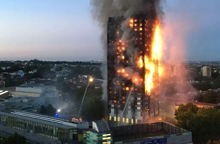
The design value of the shear force in a fire situation, Vfi,Ed at each cross section should satisfy;
Vfi,Ed/Vfi,t ,Rd ≤ 1.0 ——– (10)
where the design shear resistance Vfi,t ,Rd at time t for a Class 1, Class 2 or Class 3 cross section should be determined from:
Vfi,t ,Rd = ky,θ,webVRd [γM0/ γM,fi] ——– (11)
where;
VRd is the shear resistance of the gross cross section for normal temperature design, according to EN 1993-1-1, and given in Eq. (12);
θweb is the average temperature of the web;
ky,θ,web is the reduction factor for the yield strength of steel at the web temperature θweb.
It should be noted that when a uniform temperature is considered in the design, the average temperature in the web is equal to the uniform temperature in the section. Alternatively, the temperature in the web can be determined using the section factor of the web. For an I-section, the section factor can be approximated as kshAm / V = ksh2/tw , where the correction factor for the shadow effect is taken for the full section or, in a more accurate way, as the view factor evaluated as shown in Section 4.9.
The shear resistance of the gross cross section for normal temperature design is given (according to EN 1993-1-1) by;
Vpl,Rd = Av(fy/3)/γM0 ——– (12)
where Av is the shear area
Substituting Eq. (11) into Eq. (12), and considering a uniform temperature distribution, gives the following expression for the design shear resistance;
Vfi,t ,Rd = Avky,θfy/√3γM,fi ——– (13)
Design Example (Franssen and Real, 2015)
Consider a 3.5 m long HE 180 B column in S275 grade steel, located in an intermediate storey of a braced frame and subject to a compression load of Nfi,Ed = 495 kN in the fire situation. Assuming that the column doesn’t have any fire protection and that the required fire resistance is R30, verify the fire resistance in each of the following domains:
a) Temperature;
b) Time;
c) Resistance.
Solution:
Classification of the cross section:
The relevant geometrical characteristics of the profile for the cross section classification are;
h = 180 mm
b = 180 mm
tw = 8.5 mm
tf = 14 mm
r = 15 mm
c = b/2 − tw/2 − r = 70.75 mm (flange)
c = h − 2tf − 2r = 122 mm (web)
As the steel grade is S275
ε = 0.85 √(235/fy) = 0.786
The class of the flange in compression is
c/tf = 70.75/14 = 5.1 < 9ε = 7.07 ⇒ Class 1
The class of the web in compression is
d/tw = 122/8.5 = 14.4 < 33ε = 25.9 ⇒ Class 1
The cross section of the HE 180 B in fire situation is Class 1. This classification could be directly obtained using the table for cross sectional classification of Annex F, Vila Real et al (2009b).
Evaluation of the critical temperature:
For the HE 180 B:
Area, A = 6525 mm2
Second moment of area, Iz = 13630000 mm4
The design value of the compression load in fire situation: Nfi,Ed = 495 kN
The buckling length for intermediate storey is: lfi = 0.5L = 0.5 × 3.5 = 1.75 m
The Euler critical load takes the value:
Ncr = (π2EI)/lfi2 = 9224414 N
The non-dimensional slenderness at elevated temperature is given by Eq. (5.48)
λθ = λ ⋅√(ky,θ/kE,θ)
This is temperature dependent and an iterative procedure is needed to calculate the critical temperature. Starting with a temperature of 20ºC at which ky,θ = kE,θ = 1.0, equations (5.48), and (5.49) give:
λθ = λ ⋅√(ky,θ/kE,θ) = λ =√(Afy/Ncr) = √((6525 × 275)/9224414) = 0.441
The reduction factor for flexural buckling χ is evaluated using Eq. (5.45):
α = 0.65 √(235/fy) = 0.65 × √(235/275) = 0.601
and
φ = 0.5 × (1 + 0.601 × 0.4361 + 0.4362) = 0.730
Therefore the reduction factor for flexural buckling is:
χfi = 1/[0.730 + √(0.7302 − 0.4412)] = 0.763
The design value of the buckling resistance Nb,fi,t,Rd at time t = 0, is obtained from Eq. (5.44):
Nb,fi,0,Rd = χfiAfy / γM,fi = 1368 kN
and the degree of utilisation takes the value:
μ0 =Nfi,Ed/Nfi,0,Rd = 495/1368 = 0.362
For this degree of utilisation Eq. (5.104) gives a critical temperature, θa,cr = 635 ºC. Using this temperature, the non-dimensional slenderness λθ can be corrected, which leads to another critical temperature. The iterative procedure should continue until convergence is reached, as illustrated in the next table:
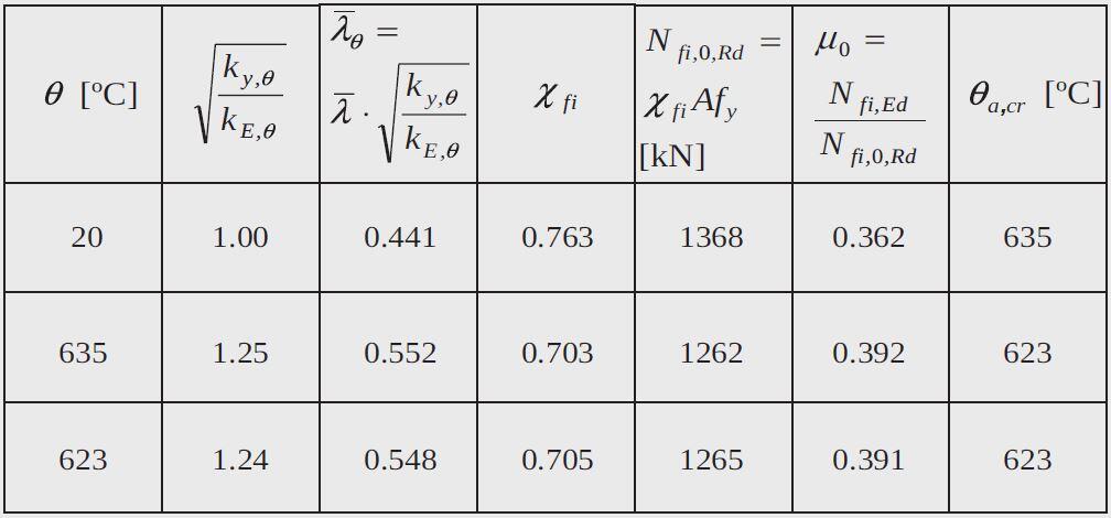
After three iterations a critical temperature of θa,cr = 623 ºC is obtained.
The verification of the fire resistance of the column may be now made.
a) The section factor of the HE 180 B is Am/V = 159 m−1 .
The box value for the section factor;
[Am/V]b = (2 × (b + h))/A = [2 × (0.18 + 0.18)]/(65.25 × 10−4) = 110.3 m−1
and the shadow factor ksh
ksh = 0.9 [Am/V]box / [Am/V] = (0.9 × 110.3 ]/159 = 0.624
The modified section factor is: ksh[Am/V]b = 0.624 × 159 = 99.2 m−1
This value could be directly obtaining from the table of Annex E, Vila Real et al (2009a). Interpolating, from table of the Annex A.4 yields the following temperature after 30 minutes:
θd = 766 ºC
and
θd > θa,cr ⇒ not satisfactory.
b) By double interpolation of table of the Annex A.4 the time needed to reach a temperature of 623 ºC is;
tfi,d = 17.4 min
and
tfi,d < tfi,requ ⇒ not satisfactory.
c) The reduction factors for the yield strength and the Young’s modulus after 30 minutes of fire exposure are, interpolating in Table 5.2 for a temperature of 766 ºC:
ky,θ = 0.1508 and kE,θ = 0.1036
The design value of the buckling resistance is obtained from;
Nb,fi,t ,Rd = χfiAky,θfy/γM,fi
The non-dimensional slenderness at 766 ºC, is
λθ = λ ⋅√(ky,θ/kE,θ) = 0.441√(0.1508/0.1036) = 0.532
and using
φθ = 0.5[ 1 + αλθ +λθ2]
with
α = 0.65 √(235/fy)
gives
φθ = 0.8014
and the reduction factor for the flexural buckling is:
χfi = 1 / [φθ + φθ2 − λθ2] = 0.714
The design value of the buckling resistance after 30 minutes of fire exposure, takes the value:
Nb,fi,t ,Rd = χfiAky,θfy /γM,fi = (0.714 × 6525 × 0.1508 × 275 × 10−3)/1.0 = 193 kN
and
Nb,fi,t ,Rd < Nfi,d ⇒ not satisfactory.
The column does not fulfil the required fire resistance R30.
References
Franssen J. and Real P. V. (2015): Fire Design of Steel Structures (2nd Edition). ECCS – European Convention for Constructional Steelwork

