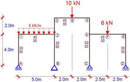
The frame shown above is supported with rollers at A, C and D, and pinned at point B. It is loaded as shown , and all columns have a cross-section of 30cm x 30cm, while the beams have a cross-section of 45cm x 30cm. Draw the bending moment diagram due to the externally applied load. Where necessary take E = 21.5 KN/mm2. In this case we are utilizing the force method, and we will apply Vereshchagin’s rule.
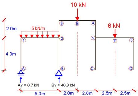
(1) First we reduce the structure to a basic system. A basic/primary system is a system that is statically determinate and stable. This is done by removing the vertical redundant supports at points C and D.
(2) We draw the bending moment for case 1 (Unit load applied at support C). X1 = 1.0
(3) We draw the bending moment for case 2 (Unit load applied at support D). X2 = 1.0
(4) We load the basic system with externally applied load and analyse it.
(5) We draw the bending moment diagram due to the externally applied load on the basic system.
(7) We write our appropriate canonical equation, and compute the influence coefficients using Vereshchagin’s rule. Solve the canonical equation and obtain X1 and X2.
(8) Substitute your final values into the Mdef equation.
(9) Plot your final moment diagram.
To download the full calculation sheet, click HERE.


