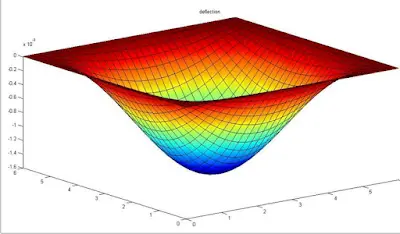
A plate is a structure whose thickness is comparatively smaller compared to its lateral dimensions. A typical example of a plate is the floor slab commonly found in our buildings. Other examples that you can think of are sheets of steel, the panes of glass windows in your homes, or even sheets of plywood. A typical concrete plate is shown in the picture below. In this post, we are interested in the linear analysis of isotropic and homogeneous plates.
Plates are used as structural members to support and transmit loads and as such, they can be subjected to bending moment, shear force, axial force, and twisting moments. The load-carrying action of a plate is similar, to a certain extent, to that of beams or cables and therefore, plates can be approximated by a gridwork of an infinite number of beams, or by a network of an infinite number of cables, depending on the flexural rigidity of the structure (Ventsel and Krauthammer, 2001).
Plates generally behave like two-dimensional structures. By implication, the loads applied on a plate are carried in two directions, and given the significant twisting rigidity of plates, a plate is stiffer than a beam of comparable span and thickness (Ventsel and Krauthammer, 2001). This two-dimensional structural action of plates results in lighter structures, and therefore offers numerous economic advantages. The bending properties of a plate depend greatly on its thickness than on any of its dimensions (Timoshenko and Woinowsky-Krieger, 1987).
Plates deform when loaded. If the deflections of a plate are small compared to its thickness, then the ‘small deformation theory’ applies, which makes the following assumptions:
1.There are no stresses in the middle plane of the plate. Hence, there are no stresses in the neutral axis during bending.
2.The points that are lying perpendicularly to the middle plane before bending remain perpendicular to the middle plane after bending.
3.The normal stresses in the transverse direction can be neglected.
By following these assumptions, the stresses on the plates can be expressed as a function of the deflection of the plate w, which is a function of the two coordinates (x,y) of the plate (Timoshenko and Woinowsky-Krieger, 1987). The governing differential equation for the deflection of thin plate under pure bending is based on the biharmonic equation shown below;
Before now, the common methods of analysis of thin plates have been the tedious classical solution using either the trigonometric or double series solution (Aginam et al, 2012). These days, numerical methods like Finite Element Method, Boundary Element Method, Finite Strip Method, Gridwork Method, Finite Difference Method, etc have become very popular due to their very easy modelling and programming into computer software.
However, finite element analysis is more prominent. In this article, the application of the finite difference method to the pure bending analysis of a thin plate simply supported on all sides has been presented. The result obtained has been compared with the results from other types of solutions.
Finite Difference Method of Analysis of Thin Plates
The finite difference method is a numerical solution to partial differential equations. When we have a function of two real variables f(x,y) that satisfies a given differential equation, we can evaluate f(x,y) numerically by laying a rectangular grid over the domain, and evaluate f(x,y) at the nodes – the points where the lines of the x-axis and y-axis intersect (For basic introduction you can see, Advanced Engineering Mathematics, Stroud and Booth, 2003).
Consider the 2-D network shown below
Let the vertical spacing of the grid be h, and the horizontal spacing be k.
From our knowledge of numerical approximation of derivatives using Taylor series expansion;
∂w/∂x = (Δx.w)/2h = (wb – wa)/2h = 1/2h [w (x + h, y) – w(x – h, y)]
∂w/∂y = (Δy.w)/2k = (wd – wg)/2k = 1/2k [w(x, y + k) – w(x, y – k)]
Analogously, for higher-order differentials;
∂2/∂x2 = ∂/∂x (∂w/∂x) = (Δx2 w)/h2 = (wb – 2w 0 – wa)/h2 = 1/h2 [w(x+h, y) – 2w(x,y) + w(x-h, y)]
∂2/∂y2 = ∂/∂y (∂w/∂y) = (Δy2 w)/k2 = (wd – 2w0 – wg)/k2 = 1/h2 [w(x, y + k) – 2w(x, y) + w(x, y – k)]
For the pure bending biharmonic equation;
(∂4 w)/∂x4 + (2∂4 w)/(∂x2 ∂y2 ) + (∂4 w)/∂y4 = P(x,y)/D, we have;
(20w0 ) – 8(wa + wb + wd + wg) + 2(wc + we + wf ) + wh ) + 1.0(wi +wj + wk + wl )= (P0 α4)/D
These expressions are often represented as patterns or computational molecules for the easy computation of the numerical solutions. The biharmonic equation pattern for computing the displacement at the interior nodes are as shown as below.
Support Conditions
For simply supported and fixed supports, we know that the deflection at those points is equal to zero. In order to formulate the boundary conditions, let us consider the interior point 0 in the figure below.
You should know that at that interior point, the biharmonic equation holds true. Let us assume that points a, c, f constitutes the boundary of the plate that is simply supported, and let node i represent a fictitious node created outside the plate boundary. A little consideration will show that for wa to be zero, we have to eliminate the deflection wi, obtained by the continuation of the network beyond the boundary of the plate. This is easily done by setting w0 = -wi for simply supported plates (See David Johnson, Advanced Structural Mechanics, 2000).
Solved Example
Let us show how the finite difference method can be applied in the analysis of thin plates subjected to uniform lateral pressure of 5 kN/m2. The plate is square with dimensions of 6m x 6m and simply supported on all sides. The data of the plate is as shown below;
The plate has been represented with gridlines that have 6 divisions on all the planar dimensions. Therefore, h = k = 1.0. This shows that the gridline aspect ratio (α) = 1.0. The gridlines have been extended by fictitious nodes, in order to capture the boundary conditions. The nodes have been numbered, and all the points where the deflections are expected to be the same due to the symmetry of the plate and the loading condition have been given the same numbering.
By implication, we have seven distinguished nodes, hence, we are going to solve a 7 x 7 matrix, which can be readily solved using Microsoft Excel or MATLAB. The computational molecule (biharmonic operator/pattern) used is the one shown below. We place the computational molecule node by node and generate the appropriate equation for each node. After the equations are generated, they are arranged as appropriate and solved. The results obtained from this method have been compared with the results from the classical solution and finite element analysis.
Since h = k, the representative computational molecule is given below;
P(x,y)/D = (P0 α4)/D
D = (Eh3) / [12(1- v2)] = (21.7 × 106 × 0.123) / [12(1 – 0.22)] = 37497.6/11.52 = 3255 kN/m2
(P0 h4)/D= (5 × 1.04/3255= 0.001536098
Node 1
20w1 – 8(4w2) + 2(4w4) + 1(4w3) = 0.001536098
Node 2
20w2 – 8(2w4 + w1 + w3) + 2(2w2 + 2w5) + 1(2w7 + w2 + 0) = 0.001536098
Node 3
20w3 – 8(2w5 + w2 + 0) + 2(2w4 + 0) + 1(2w6 + w1 + w3) = 0.001536098
Node 4
20w4 – 8(2w4 + w5 + w7) + 2(2w3 + w1 + w6) + 1(2w7 + 0 + 0) = 0.001536098
Node 5
20w5 – 8(w3 + w4 + w6) + 2(w7 + w2) + 1(w5 + w2 – w5 + 0) = 0.001536098
Node 6
20w6 – 8(w5 + w7) + 2(w4) + 1(2w3 – w6 – w6) = 0.001536098
Node 7
20w7 – 8(w3 + w4 + w6) + 2(w2 + w5) + 1(w2 + w7 – w7 + 0) = 0.001536098
Arranging in matrix form;
On solving;
w1 = 0.008059 m = 8.059mm (maximum deflection at the midspan of the plate)
w2 = 0.007062 m
w3 = 0.004202 m
w4 = 0.006192 m
w5 = 0.00369 m
w6 = 0.002211 m
w7 = 0.00369 m
On comparing with other methods;
Classical Solution from (Timoshenko and Woinowsky-Krieger, 1987, Table 8, Page 120)
Maximum deflection = 0.00406qa4/D = (0.00406 × 5 × 64)/3255 = 0.00808258 m
A little consideration will show that there is a percentage difference of 0.2917% between the answer from the classical method and FDM.
FEA result from Staad Pro (Mesh Size Division = 11 x 11)
Maximum deflection is 0.008228 m
A little consideration will show that there is a percentage difference of 2.0539% between the answer from FEM and FDM.
Conclusion
We can see that the finite difference method can be a handy solution to the analysis of thin plates. The method can be easily programmed on computer software, and the method generally yields lower bound solution.
REFERENCES
(1) Aginam C.H., Chidolue C.A., Ezeagu C.A.(2012): Application OF Direct Variational Method in the Analysis of Isotropic Thin Rectangular Plates. ARPN Journal of Engineering and Applied Sciences VOL. 7, NO. 9, ISSN 1819-6608 pp 1128 – 1138
(2) David Johnson (2000): Advanced Structural Mechanics. Thomas Telford Publishing ISBN: 0 7277 2860 1
(3)Timoshenko S. and Woinowsky-Krieger S. (1987): Theory of plates and shells (2nd Edition). McGraw Hill Book Company
(4)Ventsel E., Krauthammer T. (2001): Thin Plates and Shells Theory, Analysis, and Applications. Marcel Dekker, Inc New York. ISBN: 0-8247-0575-0
To contact the author, send an e-mail to ubani@structville.com or send a Whatsapp message to +2347053638996. Please keep visiting the blog. God bless you.
Like us on www.facebook.com/structville


this work helped me a lot, thank you for posting your work online, and that too for free. I am hoping for a little more clarity if the plate/slab is not a square.
I wanted to give a clarification for your paper. Node 5 and Node 7 are equivalent to each other. Treating them as different nodes made understanding your work much more difficult but with that issue resolved I now understand. Thank you so much for posting this work, it is great.