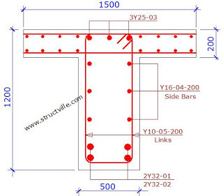
A section of a beam profile is shown above. BASED ON THE GIVEN DATA ONLY AND WITHOUT MAKING ANY ASSUMPTIONS, identify the technical error(s) in the section detailing using BS 8110-1:1997 recommendations? Read the hints below carefully!
Data
Figured dimensions are in mm
Concrete cover at the sides and the soffit = 40 mm
Concrete cover at the top = 30 mm
Strength of reinforcement = 460 N/mm2
Strength of concrete = 35 N/mm2
Section is at mid-span (sagging moment)
Area of tension reinforcement required = 2960 mm2
Hints:
(1) This post is for educational purposes, hence, your reply is better dropped here on Structville as a comment so that every person accessing the post from different platforms can see the reply.
(2) Please, do not guess. If you identify the error(s), kindly drop your comment, otherwise, keep checking back for other people’s replies. Do not post your guesses.
(3) If you are not familiar with BS 8110-1:1997, but you identify any error based on the code that you are familiar with, kindly state the code, and the error you discovered. Try to be technical in your explanations, or quote the requirement as given in the code.
(4) The diagram is not to scale, so use the figured dimensions only. Also, do not call on any data or information that is not provided.
(5) Let your explanations be offered with love.
We believe that knowledge is power.
Kindly tag all structural engineers you know and/or forward this post to them.
Our facebook page is at www.facebook.com/structville


First Obvious error is spacing between bars ( In BS8110-A : 1997 Code ) the spacing between bar and nearest shear leg must not exceed 150mm , take for example ( Tension Reinforcement : Spacing = (500-2×40-2×10-2×32)/1 = 336 which is much much more than 150mm (NOT ALLOWED) . same case for compression Reinforcement ( Spacing = (500 – 2×40-2×10-3×25)/2 = 162.5mm which is more than 150mm (NOT ALLOWED) .
There is no horizontal spacer bar between the top and bottom 2Y32s main bars.
According to BS8110 part 1 CL.3.12.11.2.6: the distribution of longitudinal spacer bars should be over a distance of 2/3 of beams overall depth measured from its tension face with spacing not exceeding 250mm.. Frm d diagram above,the longitudinal spacer bars are placed over a distance from d compression face…also using 200mm spacing, we should have 4 sets of spacer bars not 3.
This comment has been removed by the author.
Beam Bottom Bar spacing exceeds requirements provided in
Cl 3.12.11.2.3; Table 3.28 < 155 mm
Cl 3.12.11.2.4; fs = [2 (2960)Ast req]*(460)fsy*/[3 (3216)Ast prov*] = 282.26 MPa;
47000/fs < 166.51 mm
current CLEAR spacing of bottom bars both layers
= 500-2*40(cover)-2*10(link)-2*32(bars) = 336 > 155 or 166.51
Solution:- Place all Y32 bars on the same layer, hence 4T32 (B);
then the clear spacing between bars shall be = (500-2*40-2*10-4*32)/3 = 90.67 mm
which > Hagg =20 mm ~ 30 mm aggregate size (Cl3.3.1.3) + 5= 25 ~ 35mm (Cl3.12.11.1)
Beam Side Bar Spacing:-
Beam exceeds 750 mm depth Cl3.12.11.2.6 dictates side bars spacing,
currently clear spacing between side bars is (1200-2×40(cover)-25/2 (T)-32/2(B)-2×10(links))/4 (nos spacing between bars) = 267.875 mm > 250 (not ok!)
SOLUTION: create 4 nos of side bars on each side (1200-2*40-2*10-25/2-32/2)/5 = 214.3 mm Use sb = 200 mm ; b = 500 mm; fy = 460 MPa
side bar sizes can be determine from Cl 3.12.5.4; SQRT(sb*b/fy) = 14.74 mm
THEREFORE use Y16@200 c/c as side bars
From a steelfixers point of view it needs another two y32 mm in the bottom with a shear link around the y25s at the top in the middle taking in the two y32s in the bottom with additional spacing bars for the t32s,the side bars are fine
Very interesting contribution and good knowledge of the code… Thanks
Well, how did you know? But the drawing clearly showed that there is spacing between the two bars. But since the data was not provided….
Thanks for your contribution… I appreciate
if slab is continues then it should be like continue mark if not then cover is missing & slab reinforcement marking missing
Since its has flanges, At d support, moment is negative so tension will be at the top fibers nd compression buttom. So the top suppose to be more reinforced than d bottom
No top reinforcements are provided for the beam against the slab. Moreover, the spacing along the beam's cross-section is more than 300mm.
This comment has been removed by the author.
OK. Thanks
Nice one. Thank you sir
Heya! I just wanted to ask if you ever have any problems with hackers? My last blog (wordpress) was hacked and I ended up losing many months of hard work due to no data backup. Do you have any solutions to protect against hackers? gmail.com login
BS 8110-1: 1997
3.4.5.13 Torsion
In normal slab-and-beam or framed construction specific calculations are not usually necessary, torsional cracking being adequately controlled by shear reinforcement but when the design relies on the torsional resistance of a member, explicit design for torsion will be necessary. RECOMMENDATIONS are given in 2.4 of BS 8110-2:1985
BS 8110-2 1985 ;
2.4.7 Area of torsional reinforcement;
2.4.8 Spacing and TYPE of LINKS (see embedded figure & compare with the structl detailing);
2.4.9 Arrangement of longitudinal torsion reinforcement;
2.4.10 Arrangement of links in T-, L- or I-sections…
——–
Longitudinal bottom bars as well will need to be re-oriented for better tensile cap.
• It is appropriate time to make a few plans for the future and it is time to be happy. I have learn this publish and if I may just I desire to recommend you some attention-grabbing things or tips. Perhaps you can write next articles relating to this article. I want to read more issues about it!.
COBie adaptation in India
Construction Documentation in India
Y32’s could have been placed all in the bottom row providing deeper lever arm of the beam
So is there an official right answer(s) to this old post or is it just an open discussion?