Several codes of practice in the world allow us to idealise structures into 2-dimensional frames for simplified analysis. For sub-frames, it is obvious that the force method becomes less handy due to the high number of redundants, and the next best alternative is the displacement method (stiffness method), where we solve for the unknown displacements.
The displacement method, also known as the stiffness method, has become a cornerstone of structural analysis. It offers a powerful and versatile framework for solving equilibrium problems in various structures, from trusses and beams to complex frames and continua.
At its core, the stiffness method focuses on determining the unknown displacements of points within a structure under the action of applied loads. This is achieved by establishing a relationship between the displacements and the internal forces generated within the structure. This relationship is expressed through the stiffness matrix, which encodes the inherent rigidity of the structure and its resistance to deformations.
Solved Example Using the Stiffness Method
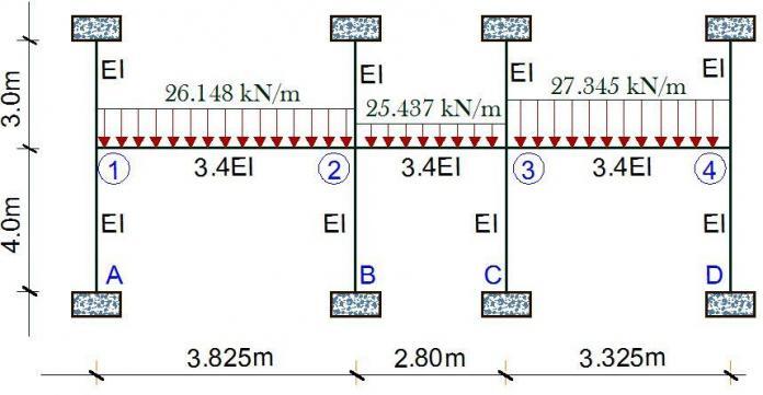
In this article, we have a typical example where a problem that would have generated a (21 x 21) matrix using the force method, has been solved using a (4 x 4) matrix by the stiffness (displacement) method. Another approach to the solution of this problem is the moment distribution method. But in this case, the stiffness method remains the fastest.
For the frame loaded as shown above, we have to start by drawing the kinematic basic system of the structure. This has been achieved by fixing the nodes 1, 2, 3 and 4 against rotation as shown below.
We will now have to evaluate the basic system for different cases of a unit rotation Zi = 1.0, applied at the fixed nodes.
Analysis of Case 1
Z1 = 1.0; Z2 = Z3 = Z4 = 0
K11 = (4EI/3) + (4EI/4) + (13.6EI/3.825) = 5.889EI
K21 = (6.8EI/3.825) = 1.778EI
K31 = 0
K41 = 0
Analysis of Case 2
Z2 = 1.0; Z2 = Z3 = Z4 = 0
K12 = (6.8EI/3.825) = 1.778EI
K22 = (4EI/3) + (4EI/4) + (13.6EI/3.825) + (13.6EI/2.8) = 10.7460EI
K32 = (6.8EI/2.8) = 2.4286EI
K42 = 0
Analysis of Case 3
Z3 = 1.0; Z1 = Z2 = Z4 = 0
K13 = 0
K23 = (4EI/3) + (4EI/4) + (13.6EI/3.825) + (13.6EI/2.8) = 10.7460EI= 2.4286EI
K33 = (4EI/3) + (4EI/4) + (13.6EI/3.325) + (13.6EI/2.8) = 11.2807EI
K43 = (6.8EI/3.325) = 2.0451EI
Analysis of Case 4
Z4 = 1.0; Z1 = Z2 = Z3 = 0
K14 = 0
K24 = 0
K34 = (6.8EI/3.325) = 2.045EI
K44 = (4EI/3) + (4EI/4) + (13.6EI/3.325) = 6.4236EI
Stiffness coefficient due to externally applied load;
K1P = -(q1L12/12) = -(26.148 × 3.8252) / 12 = -31.880 kNm
K2P = (q1L12/12) – (q2L22/12) = [(26.148 × 3.8252) / 12] – [(25.437 × 2.802) / 12] = 15.261 kNm
K3P = (q2L22/12) – (q3L32/12) = [(25.437 × 2.82) / 12] – [(27.345 × 3.3252) / 12] = -8.5741 kNm
K4P = (q3L32/12) = (27.345 × 3.3252) / 12 = 25.193 kNm
The appropriate cannonical equation;
K11Z1 + K12Z2 + K13Z3 + K14Z4 + K1P = 0
K21Z1 + K22Z2 + K23Z3 + K24Z4 + K2P = 0
K31Z1 + K32Z2 + K33Z3 + K34Z4 + K3P = 0
K41Z1 + K42Z2 + K43Z3 + K44Z4 + K4P = 0
On substituting;
5.889Z1 + 1.778Z2 + 0Z3 + 0Z4 = 31.880
1.778Z1 + 10.746Z2 + 2.4286Z3 + 0Z4 = -15.261
0Z1 + 2.4286Z2 + 11.287Z3 + 2.045Z4 = 8.5741
0Z1 + 0Z2 + 2.045Z3 + 6.4236Z4 = -25.193
On solving;
Z1 = 6.3102/EI (radians)
Z2 = -2.9701/EI (radians)
Z3 = 2.2384/EI (radians)
Z4 = -4.6346/EI (radians)
Now that we have obtained the rotations, we can now substitute and obtain the moments at the critical points;
Mi = M1Z1 + M2Z2 + M3Z3 + M4Z4 + P
Bottom column support moments
MA = (6.3102/EI) × (2EI/4) = 3.1551 kNm
MB = (-2.9701/EI) × (2EI/4) = -1.485 kNm
MC = (2.2384/EI) × (2EI/4) = 1.1192 kNm
MD = (-4.6346/EI) × (2EI/4) = -2.3173 kNm
Beam Support Moments
M1R = [(6.3102/EI) × (13.6EI/3.825)] – [(2.9701/EI) × (6.8EI/3.825)] – 31.880 = -14.7239 kNm
M2L = [(6.3102/EI) × (6.8EI/3.825)] – [(2.9701/EI) × (13.6EI/3.825)] + 31.880 = 32.537 kNm
M2R = [-(2.9701/EI) × (13.6EI/2.8)] + [(2.23841/EI) × (6.8EI/2.8)] – 16.619 = -25.6090 kNm
M3L = [-(2.9701/EI) × (6.8EI/2.8)] + [(2.2384/EI) × (13.6EI/2.8)] + 16.619 = 20.278 kNm
M4R = [(2.2384/EI) × (13.6EI/3.325)] – [(4.6346/EI) × (6.8EI/3.325)] – 25.193 = -25.5157 kNm
M3L = [(2.2384/EI) × (6.8EI/3.325)] – [(4.6346/EI) × (13.6EI/3.325)] + 25.193 = 10.814 kNm
Thank you for visiting Structville today….
Our Facebook page is at www.facebook.com/structville


Hello Bro,
The coefficient stiffness 13.6 i'm not seeing where it's derived from? Can you explain how you derived it? thanks
Fc
Sorry that I did not make the post very 'down to earth'. The moment from unit rotation at any near end is given by 4EI/L and at any far end is 2EI/L.
So 4 x 3.4EI = 13.6EI/L
The beam stiffness was given, I missed that! Just to be clear, the beam stiffness is factored up due to the column stiffness, this is my understand.
What if the upper column had a smaller stiffness compared to the lower column would it be and average factor times the beam stiffness?
Thanks
Frank
No, there is nothing like average in handling relative stiffness of Structural members. Note that there is no rule that you must work in terms of column stiffness. You can also work in terms of beam stiffness.
For example, if the upper column has lesser stiffness, we can have something like; 0.75EI for upper column, EI for lower column, and 3.4 EI for beams.
This comment has been removed by the author.
(y)
Where did the 3.4 in 3.4EI come from?
It simply means that the flexural rigidity of the beams is 3.4 times higher than that of the columns. It is usually due to a difference in the geometry of the sections.
For instance if the beam is a T-beam with a flange width of 1500mm, and the columns are just 230 x 230mm, you should expect a significant difference in their flexural rigidity (EI).
If we assume that the bottom column ends are pinned to foundation, how do we solve the problem? In the book “Designed and Detailed (BS 8110 : 1997) authored by J.B. Higgins and B.R. Rogers and published by British Cement Association (BCA) – A multi Storey Building has been designed using sub frame analysis, assuming bottom columns pinned at foundation level. But calculations are not given. It says that “A linear elastic analysis either produced by hand or by computer program is used to obtain the moments and forces”. I such a case will there be a change in moments and forces at beam-column joints at first floor level.
I am a civil engineer in Sri Lanka. Thank You.
How do we proceed if the bottom columns are assumed pinned at foundation level?
Will there be any changes in moments at beam-column joints at floor level.
Thank you.
I found the method.
In such a case, the respective Beam Stiffness have to be taken as 0.75 of the normal stiffness.
The results obtained tally with the results of the reference book.
I solved both examples using SMath Studio programming language which is totally free.
I will be happy to share if anyone needs them.
Thank you so much.