Structural analysis is an important aspect of any structural design. It is simply the process of determining the effect of direct and indirect actions on structures. The effects of actions usually obtained from structural analysis are the displacements, bending moment, shear forces, axial forces, torsion, etc. Linear first-order analysis of statically indeterminate frames can be carried out using the force method, displacement methods, or other approximate solutions.
It is a well-known fact that there are two basic methods of analysing statically indeterminate structures which are;
- Flexibility methods (also known as force methods, compatibility methods, or the method of consistent deformations), and
- Displacement methods (also known as stiffness or equilibrium method)
Each method involves the combination of a particular solution which is obtained by making the structure statically determinate and a complementary solution in which the effect of each individual modification is assessed. In the force methods, the behaviour of the structure is considered in terms of unknown forces, while in the stiffness method, the behaviour of the structure is considered in terms of unknown displacements.
By implication, both analysis methods always involve reducing the structure to a basic system (a determinate system). In the force method, the basic system involves the removal of redundant forces, while the stiffness method involves restraining the joints of the structure against displacement.
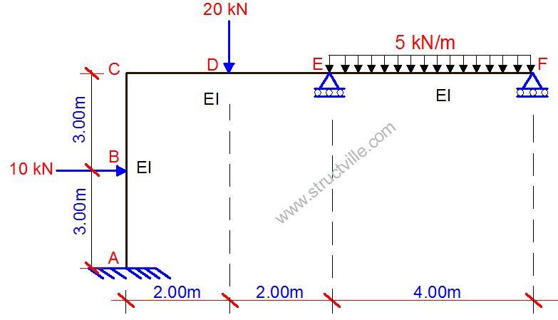
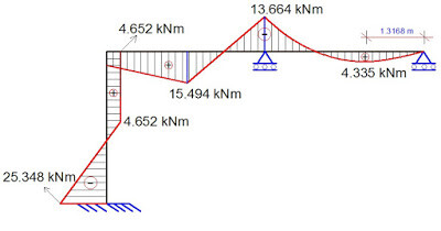
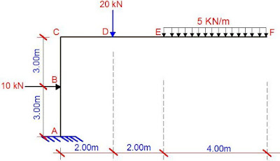
In the solved example downloadable from this post, the frame shown above has been analysed for bending moment due to the externally applied load using force method and displacement method. In the force method, the graphical method was employed (Vereschagin’s rule of diagram multiplication).
To get yourself familiar with Vereschagin’s rule, click HERE
To see an elaborate example of its application, click HERE;
Highlights of the solved problem
NOTE: Diagrams are not to scale. Read assigned values
Analysis of Frames using the Force Method
Step 1: Calculate the degree of static indeterminacy of the structure
D = (3M + R) – 3N
Where; M = Number of members; R = Number of support reactions; N = Number of nodes
In this case; D = (3 x 3 + 5) – (3 x 4) = 2
Therefore the structure is statically indeterminate to the 2nd order
Step 2: Reduce the structure to a basic/primary system by removing redundant supports and replace them with unit loads (X1 and X2)
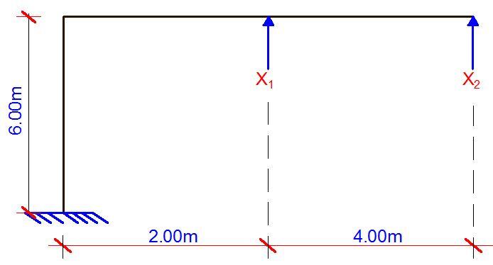
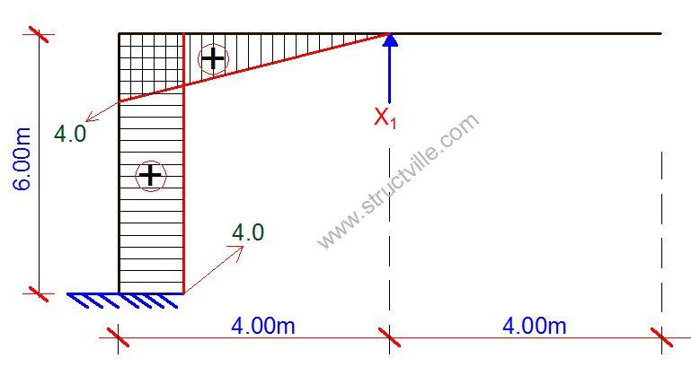
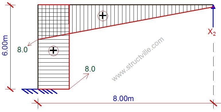
Step 3: Analyse the primary system for the various unit loads, treating each as a separate load case.
Case 1
Case 2
Step 4: Analyse the primary system when subjected to the external load, and plot the internal forces diagram.
Step 5: Compute the influence coefficients by diagram multiplication
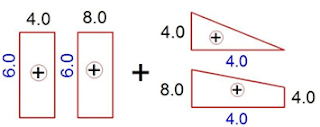
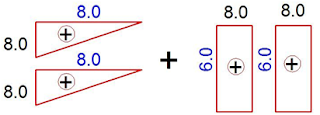
A few examples of how the bending moment diagrams from above are combined are shown in the figures below.
δ11 – Deformation at point 1 due to unit load at point 1. In this case, the bending moment diagram from case 1 is combining with itself;
δ12 = δ21 – Deformation at point 1 due to unit load at point 2 (this is equal to the deformation at point 2 due to unit load at point 1). In this case, the bending moment from case 1 is combining with the diagram from case 2.
δ22 – Deformation at point 2 due to unit load at point 2. Here, case 2 bending moment diagram is combining with itself;
Δ1P – Deformation at point 1 due to externally applied load. Here, the bending moment from case 1 is combined with the bending moment from the externally applied load.
Δ2P – Deformation at point 2 due to externally applied load. Here, the bending moment from case 2 is combining with the bending moment from the externally applied load.
Step 6: Formulate the appropriate cannonical equation, and solve for the reactive forces X1 and X2
δ11X1 + δ12X2 + Δ1P = 0
δ21X1 + δ22X2 + Δ2P = 0
Step 7: Compute the final values of the internal forces
Mdef = M0 + M1X1 + M2X2
Step 8: Plot the internal stresses diagram
Analysis of Frames using the Displacement Method
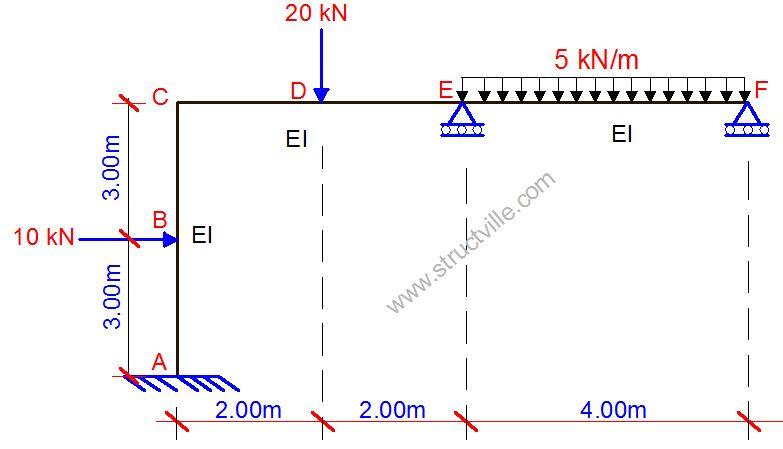
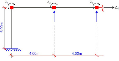
Step 1: Calculate the degree of kinematic indeterminacy. This is the number of unknown nodal displacements that the structure can undergo. They are generally nodal rotations and linear translations. In this example, the structure has unknown displacements at joint C (unknown rotation), joint E (unknown rotation), joint F (unknown rotation), and a lateral displacement (side sway) that is represented at joint F. Therefore it is kinematically indeterminate to the 4th degree.
Step 2: Reduce the structure to the primary system by restraining all unknown displacements. Apply unit displacements at the joints so restrained (Z1, Z2, Z3 and Z4)
Step 3: Analyse the structure for the various unit displacements, treating each as a separate load case.
Case 1; Z1 = 1.0
Case 2; Z2 = 1.0
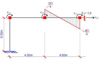
Case 3; Z3 = 1.0
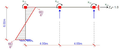
Case 4; Z4 = 1.0
Step 4: Compute the stiffness coefficients for each load case by considering reactions due to unit displacement at the fixed ends. In all cases, Kij stands for the force at point i due to unit displacement at point j.
Step 5: Compute the free terms of the canonical equation for each node from the fixed end moments and reactive forces due to the externally applied load.
Step 6: Formulate the appropriate canonical equation, and solve for the real nodal displacements
Solve for Z1, Z2, Z3, and Z4
Step 7: Substitute back and obtain the final values of the bending moment
Mdef = MO + M1Z1 + M2Z2 + M3Z3 + M4Z4
Step 8: Plot the internal stresses diagram
To download the full solved paper in printable PDF format, click HERE

