Question
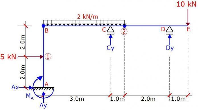
A frame is loaded as shown above. There are internal hinges at nodes B and 2. Plot the internal stresses diagram due to the externally applied load.
Solution
Check for static determinacy.
A quick but non-general way of verifying degree of static indeterminacy of simple frames is;
D = R – e – S
where;
D = Degree of static indeterminacy
R = Number of support reactions = 5
e = Number of static equilibrium equations = 3
S = Number of special condition = 2 ( internal hinges)
D = 5 – 3 – 2 = 0
Therefore, the structure is statically determinate and stable.
Read also in this blog….
Static Determinacy of Rigid Frames
Understanding Sign Conventions in Structural Analysis
Support Reactions
Let ∑FX = 0
Ax + 5 = 0
Ax = -5 KN ←
Let ∑M2R = 0
2Dy – (10 × 3) = 0
Dy = 15 KN
Let ∑MBR = 0
6Dy + 3Cy – (10 × 7) – ((2 × 42)/2) = 0
6(15) + 3Cy – 70 – 16 = 0
Cy = -1.333KN↓
Let ∑MBB = 0
Note that the due to the direction of the horizontal reaction A, it will exert a positive moment about column AB. Therefore;
4Ax – (5 × 2) – MA = 0
4(5) – 10 = MA
MA = 10 KN.m
Let ∑M2L = 0
4Ay + 4Ax + Cy – MA – ((2 × 42)/2) – (5 × 2) = 0
4Ay + 4(5) – 1.333 – 10 – 16 – 10 = 0
Ay = 4.333 KN
Equilibrium check;
∑FY ↓ = (2 × 8) + 10 = 18KN
∑FY ↑ = 15 – 1.333 + 4.333 = 18KN OK
| Fig 1: Support Reactions Due to Externally Applied Load |
Analysis of Internal forces
Section A – 1 (0 ≤ y ≤ 2.0m)
(i) Bending Moment
My = 5y – 10 ———— (1)
At y = 0;
MA = -10 kNm
At y = 2.0m;
M1B = 5(2) – 10 = 0
(ii) Shear Force
The section is subjected to constant shear force;
Qx = ∂My/∂y = 5 KN
(iii) Axial Force
Ny + 4.333 = 0
NA-1 = -4.333 KN (compression)
Section 1 – B (2.0m ≤ y ≤ 4.0m)
(i) Bending Moment
My = 5y – 5(y – 2) – 10 ———— (2)
At y = 2m;
M1UP = 5(2) – 10 = 0
At y = 4.0m;
MBB = 5(4) – 5(2) – 10 = 0
This shows that there is no bending moment at this section.
(ii) Shear Force
Differentiating equation (1) above yields zero. Therefore, there is shear force at the section also.
(iii) Axial Force
Ny + 4.333 = 0
N1-B = -4.333 KN (compression)
Section B – C (0 ≤ x ≤ 3.0m)
(i) Bending Moment
Mx = 4.333x – x2 ———— (3)
At x = 0;
MBR = 0
At x = 3.0m;
MCL = 4.333(3) – (3)2 = 4 KNm
Maximum moment occurs at the point of zero shear. Therefore;
Qx = ∂Mx/∂x = 4.333 – 2x = 0
On solving;
x = 4.333/2 = 2.1665m
Mmax = 4.333(2.1665) – (2.1665)2 = 4.693 KNm
(ii) Shear Force
The section is subjected to constant shear force;
Qx = ∂Mx/∂x = 4.333 – 2x
At x = 0;
QBR = 4.333 KN
At x = 3.0m;
MCL = 4.333 – 2(3) = -1.667 KN
(iii) Axial Force
Nx = 0
No axial force
Section C – 2 (3.0m ≤ x ≤ 4.0m)
(i) Bending Moment
Mx = 4.333x – 1.333(x – 3) – x2 ———— (4)
At x = 3m;
MCR = 4.333(3) – 32 = 4 KNm
At x = 4.0m;
M2 = 4.333(4) – 1.333(1) – (4)2 = 0
(ii) Shear force
Expanding equation (4) above;
Mx = –x2 + 3x + 4
Qx = ∂Mx/∂x = -2x + 3
At x = 3m
QCR = -2(3) + 3 = -3 KN
At x = 4m
Q2L = -2(4) + 3 = -5 KN
(iii) Axial Force
No axial force
Section D – E (0 ≤ x ≤ 1.0)
(i) Bending Moment
Mx = -10x ————— (5)
At x = 0;
ME = 0
At x = 1.0m;
MCL = -10(1) = -10 KNm
(ii) Shear Force
Qx = ∂Mx/∂x = -10 KN
But since we are coming from the right to the left, downward force is positive.
Therefore the section subjected to a positive constant shear force of 10 KN
(iii) Axial force
There is no axial force at the section
Internal Stresses Diagram
We can now plot the internal stresses diagram from the values obtained above.
| Fig 2: Final Bending Moment Diagram |
| Fig 3: Final Shear Force Diagram |
| Fig 4: Final Axial Force Diagram |
Thank you for visiting Structville today.
Join our exciting facebook interactive page at www.facebook.com/structville


I love this, I’ll like to always be part of such great work