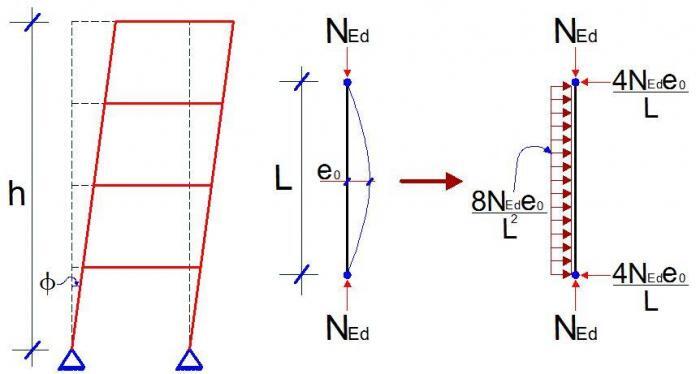
Imperfection in structures can be described as deviations and inconsistencies in structures and structural members, which can affect the behaviour of the structure from the theoretically assumed perfect state. Imperfections in structures are often envisaged during analysis, and their effects are taken into consideration, especially in cases where they could be critical.
Types of Imperfections
Different types of imperfections are considered in structural analysis and they are;
(i) Geometrical imperfection
(ii) Material imperfection
(iii) Structural imperfection
Geometrical Imperfection
As the implies, these are imperfections due to variance in the dimensions of the members, or lack of straightness or verticality in a structural member.
For example, when a beam member that is supposed to be 400mm depth is finished as 395mm, then this is geometric imperfection. According to clause 5.2(1)P of Eurocode 2, deviation in members cross-section is normally taken into account in material partial factor of safety, and may not need to be analysed for again.
Also, when a 2-storey framed building that is supposed to be perfectly straight/vertical is leaning by say an angle of 3 degrees, this is also geometric imperfection. This form of geometric imperfection is taken into account when analysing sensitive structures.
Material imperfection
This type of imperfection always arises from deviation in the assumed material properties. For instance, if the design engineer specified a concrete grade of M30, and grade 28.5 was achieved on site, then this is material imperfection. Also, when the modulus of elasticity of steel specified was 200 kN/mm2 and 195 kN/mm2 was fabricated, this is also material imperfection. Another variance in material imperfection is residual stresses, which occurs in steel members during welding or fabrication.
Material imperfection is often taken care of by introducing material factor of safety in design.
Structural Imperfection
Structural imperfection often arises in structures due to issues like eccentricity in joints, variations in support/boundary conditions, variation in stiffness/rotation of joints.
Analysis of Imperfections in Structures
In frames, all types of imperfections are usually introduced as equivalent geometrical imperfections with increased value of amplitude e0d, while in plated structures, geometric imperfections and residual stresses are introduced to derive buckling factors.
According to clause 5.3.1(1) of Eurocode 3, the following imperfections should be taken into account;
a) global imperfections for frames and bracing systems
b) local imperfections for individual members
Global imperfections for frames or bracing systems cover for lack of verticality for frames or straightness of structures restrained by bracings, while local imperfections cover for lack of straightness or flatness of a member and residual stresses of the member.
We should note that other imperfections are covered by the partial factors in limit state design.
Global Imperfection Analysis for frames
In framed structures, the assumed shape of global imperfection may be derived from the elastic buckling mode of the the structure in the plane considered. For frames sensitive buckling in sway mode (e.g. tall buildings), the effect of imperfection is allowed for by means of equivalent imperfection in the form of an initial sway imperfection.
The effects of initial sway imperfection may be replaced by systems of equivalent horizontal forces. These initial sway imperfections are applied in all relevant horizontal directions, but need only be considered in one direction at a time. For multi-storey buildings, equivalent forces are used and they should be applied at each floor and roof level.
The imperfections may be determined from;
ϕ = ϕ0αhαm
where;
ϕ0 is the basic value = 1/200
αh is the reduction factor for height applicable to columns
αh = 2/√h but 2/3 ≤ αh ≤ 1.0
αm is the reduction factor for number of columns in a row
where m is the number of columns in the row.
A schematic diagram showing the representation of sway imperfections with equivalent horizontal loads is shown below;
According to clause 5.3.2(4)B, building frames sway imperfections may be disregarded whenever HEd ≥ 0.15 VEd
Solved Example
Let us carry out the global sway imperfection of the frame loaded as shown below.
BEAMS – UB 305 x 102 x 28
Solution
∑HEd = 15 + 23 + 45 = 83 kN
0.15∑VEd = 0.15(25 + 65 + 25 + 70 + 126 + 70 + 145 + 209 + 145) = 132 kN
Since HEd < 0.15 VEd sway imperfection will need to be considered.
αh = 2/√h = 2/√12 = 0.577 since it is < 2/3, take 2/3 (check specified limits)
m = 3 (3 columns in a row)
αm = sqrt [0.5 × (1 + 1/3)] = 0.8165
Therefore;
ϕ = ϕ0αhαm = (1/200) × (2/3) × (0.8165) = 0.00272
Therefore,
At the roof level, imp1 = ϕV1 = 0.00272 × (25 + 65 + 25) = 0.3128 kN
At the second floor, imp2 = ϕV2 = 0.00272 × (70 + 126 + 70) = 0.7235 kN
At the first floor, imp3 = ϕV3 = 0.00272 × (145 + 209 + 145) = 1.357 kN
These imperfections belong to each cross frame (bay). For the double bay frame in our example, the imperfection will need to be doubled;
Analysing the structure using StaadPro;
Analysis Results
The moment diagram below is for the external load only without the effect of imperfections.
The moment diagram below is for external load with the effect of imperfection inclusive.
Analysis of results
Maximum Moment on ground floor column without the effect of imperfection (column at RHS) = 99.979 kNm
Maximum Moment on ground floor column with the effect of imperfection (column at RHS) = 109.048 kNm
This is about an 8.316% difference in the bending moment value.
A little consideration will show that for axial loads also;
Maximum axial load without the effect of imperfection (middle column) = 398.394 kN
Maximum axial load with the effect of imperfection (middle column) = 398.383 kN
This shows that these imperfections have more effect on the bending moment of the structure than on the axial load.
For shear force on the columns, a difference of about 8.123% was observed.
Our facebook page is at www.facebook.com/structville


Guys which imperfection calculation is proper for inclined column to full fill geometric inclination
Am happy with is analysis most of the time in manual calculations we don’t consider.