According to clause 4.1 of EN 1992-1-1:2004, a durable structure should meet the requirements of serviceability, strength and stability throughout its design working life, without significant loss of utility or excessive unforeseen maintenance.
 |
| Fig. 1: Typical Carbonation Problem Leading to Lack of Durability in a Reinforced Concrete Structure |
The required protection of any structure is established by considering the intended use of the structure, the design working life, maintenance programme, significance of possible direct and indirect actions, environmental conditions etc. Environmental conditions that can be considered may include storage of aggressive chemicals, chlorides in the concrete, acid solutions, alkali-aggregate reactions etc which are generally categorised as chemical attacks. Issues like abrasion, water penetration, temperature change etc are categorised as physical attacks.
According to clause 4.3 of Eurocode 2, in order to achieve the required design working life of a structure, adequate measures shall be taken to protect each structural element against the relevant environmental actions. The requirements for durability shall be included when considering the following:
- Structural conception,
- Material selection,
- Construction details,
- Execution,
- Quality Control,
- Inspection,
- Verifications,
- Special measures (e.g. use of stainless steel, coatings, cathodic protection).
An important aspect of durability of reinforced concrete structure is the anticipated exposure of the element under consideration. Some exposure conditions are given in the table below (Table 4.1 of EN 1992-1-1:2004);
2.0 Concrete Cover
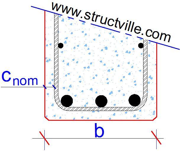
Concrete cover is the distance between the surface of the reinforcement closest to the nearest concrete surface (including links and stirrups and surface reinforcement where relevant) and the nearest concrete surface.
Concrete cover is defined as a minimum cover, cmin, plus an allowance in design for deviation, Δcdev;
cnom = cmin + Δcdev ———- (1)
Minimum concrete cover, cmin, shall be provided in order to ensure the safe transmission of bond forces, protection of the steel against corrosion (durability) and for an adequate fire resistance.
The greater value for cmin satisfying the above mentioned requirements shall be used. This is given by;
cmin = max {cmin,b; cmin,dur + Δcdur,γ – Δcdur,st – Δcdur,add; 10 mm} ———- (2)
where;
cmin,b is the minimum cover due to bond requirement
cmin,dur is the minimum cover due to environmental conditions
Δcdur,γ is for additive safety element
Δcdur,st is the reduction of minimum cover for use of stainless steel
Δcdur,add is the reduction of minimum cover for use of additional protection
In order to transmit bond forces safely and to ensure adequate compaction of the concrete,
the minimum cover should not be less than cmin,b given in Table 4.2 of EN 1992-1-1:2004 and given in Table 2 below;
3.0 Solved Example
Design the concrete cover of an external reinforced concrete beam.. The concrete in use has resistance class C30/37.
Bottom longitudinal bars are H16; the stirrups are H8
The design working life of the structure is 50 years.
Normal quality control is put in place.
Solution


