Precise moment distribution is a variation of moment distribution method which aims to shorten the time spent carrying out the normal moment distribution method. This is achieved by introducing continuity and distribution factors, which in turn means that only one distribution and carry over is required to achieve the final bending moment values. This post explores this method of structural analysis, and a solved example is used to drive the point home.
[the_ad id=”498″]
Procedure for Carrying Out Precise Moment Distribution method (Reynolds and Steedman, 2005)
(1) Calculate fixed end moments
(2) Determine continuity factor for each span from the general expression;
Where;
ϕn+1 and kn+1 are continuity and stiffness of span being considered
∑[kn/(2 – ϕn)] is the sum of values of [kn/(2- ϕn)] of all remaining members meeting at that joint
If far end of column is fully fixed, then [kn/(2- ϕn)] = 2kn/3, since ϕn = 0.5
If far end of column is pinned, then [kn/(2- ϕn)] = kn/2
You have to work from left to right, and from right to left
(3) Calculate distribution factors at joints from general expression;
Where ϕBC and ϕCB are continuity factors obtained from step 2.
Unlike in continuous beams, sum of distribution factors each side of support will not equal to unity due to action of columns. Distribution factor for each column is obtained by dividing total column distribution factor in proportion to stiffness of columns.
(4) To carry over moment at supports, multiply distributed balancing moment at left hand end of member by continuity factor obtained from working RIGHT to LEFT, and carry over this value to the right hand side. At this point balance carried over moment by dividing an equal amount of opposite sign between then remaining members meeting at that joint with respect to their values of [kLR/(2- ϕRL)]
(5) Undertake one complete carry over operation working from left to right and then from right to left from each joint at which fixed end moment occurs and sum results to obtain final moment of the system.
READ ALSO……
Analysis of sub frames using Using Stiffness Method
How to Succeed as A Civil Engineering Student
Solved Example
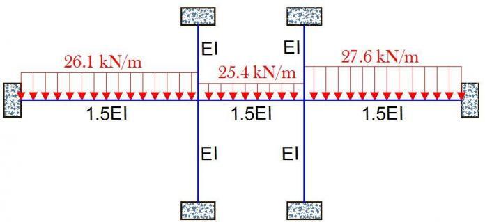
For the non-sway frame loaded as shown below, obtained the bending moments on the frames using precised moment distribution method.
Solution
(1) Fixed End Moment
FCD = qL2/12 = (-15 × 82)/12 = -80 kNm
FDC = qL2/12 = (15 × 82)/12 = 80 kNm
Relative Stiffnesses
For columns K = 2EI/h = 2/3
For beam K = EI/L = 1/8
For columns with far ends fully fixed;
2kn/3 = 2(2/3)/3 = 4/9
Continuity factors
Distribution Factors (DF)
DFCD = DFDC = (1 – 2ϕCD)/(1 – ϕCDϕDC)
DFCD = DFDC = (1 – 2 × 0.467) / (1 – 0.467 × 0.467) = 0.0844
The remaining distribution factor at each node = 1 – DFCD = 1 – 0.0844 = 0.9156
This distribution factor is now shared among the columns according to their stiffnesses. Since the stiffnesses are equal = 0.9156/2 = 0.4578
Now the moments are distributed by multiplying the fixed end moments by the distribution factor in the opposite sign.
E.g For the left hand side of the beam; M = -80 × 0.084 = +6.72 (note the change in sign)
For the upper column (UC) ; M = -80 × 0.458 = +36.64 (note the change in sign)
Using this same approach, you can compute the remaining.
Carry over
The moment of +6.72 is carried over from DC to CD based on the continuity factor, and once again this is done with the reverse sign (check step 4 above).
For instance, +6.72 is multiplied by 0.467 which gives -3.138 (note the change in sign).
This moment of -3.138 is shared in opposite sign to the remaining members in the proportion of their [kLR/(2 – ϕRL)].
For instance for the columns, [kLR/(2 – ϕRL)] = [(2/3) /(2 – 0.467)] = 0.4348
For the beam, [kLR/(2 – ϕRL)] = [(1/8) /(2 – 0.467)] = 0.08155
Now, the moment shared to each column (in opposite sign) is given by;
MUC = MLC = -3.138 × [0.4328/(0.4348 + 0.4348 + 0.08155] = 2.282 kNm
READ ALSO…..
21 Things you should know about blast resistant buildings
The final moments are now obtained by summing up the fixed end moment, the distributed moment, and the carried over moment.
These steps are normally prepared using the simple table below;
UC = Upper column; LC = Lower Column
To verify our result, kindly look at the result from Staad Pro for the same frame;
Thank you for visiting structville today.
Have you read?
Hope for Fresh Graduate Engineers
Anyway, our amazing facebook page is at;
www.facebook.com/structville


For the mathematical computation that gives the value of the moment shared to each column:
1, Where did you get 0.4328 from?
2. If you I plug your values in that formula, I get -1.428 and not 0.282 as you show. This, in turn, will affect the distribution and computation in your table.
By the way, this is a very nice example. This is the only one I was able to find in Google search.
Thank you!