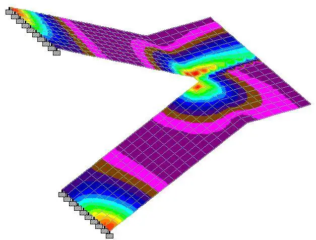
Free-standing staircases offer a very pleasing solution for vertical circulation in residential and commercial buildings. They are usually constructed in such a way that the landing is freely supported, while the supports at the flight are fully fixed. It is possible to have the flights supported in other ways, but that makes the analysis more complicated. Freestanding staircase structures are complex in analysis and design, but with finite element analysis packages, simple solutions can be easily obtained as shown in this post.
The most widely available manual solution for the analysis of free-standing staircases was developed by Cusens and Kuang using the strain-energy principles. Expressions were developed relating the horizontal restraint force H and the bending moment Mo at the mid-point of the free-standing stair. By solving both equations simultaneously, the values of Mo and H can be substituted into the general expressions to obtain the bending moments and forces at any point in the structure.
In this article, we are going to compare the results obtained with Staad Pro software with results from manual analysis using the method proposed in Table 175, Reynolds and Steedman, 2005.
Dimensions
Solved Example
The geometry of a free-standing staircase is given below. We are expected to analyse the staircase for the ultimate moment using the formula given in Reynolds and Steedman (2005) and compare the answer with the result from Staad Pro.
Data
Thickness of waist of flight and landing = 250 mm
Depth of riser = 150mm
Unit weight of concrete = 25 kN/m3
Actions on the stairs
Concrete self weight (waist area) = 0.25 × 25 = 6.25 kN/m2 (normal to the inclination)
Stepped area = 1⁄2 × 0.15 × 25= 1.875 KN/m2 (global vertical direction)
Finishes (say) = 1.2 kN/m2
We intend to apply all gravity loads purely in the global y-direction, therefore we convert the load at the waist of the stair from local to global direction by considering the angle of inclination of the flight area to the horizontal;
γ = tan-1(1.5/3) = 26.565°
Therefore UDL from waist of the stair in the global direction is given by = (6.25 × cos 26.565) = 5.59 kN/m2
Total permanent action on flight area (gk) = 5.59 + 1.875 + 1.2 = 8.665 kN/m2
Total permanent action on landing; (gk) = 6.25 + 1.2 = 7.45 kN/m2
Variable load on staircase (qk) = 4 kN/m2
The load on the flight area at ultimate limit state = 1.35gk + 1.5qk
nf = 1.35(8.665) + 1.5(4) = 17.67 kN/m2
The load on the landing at ultimate limit state = 1.35gk + 1.5qk
nl = 1.35(7.45) + 1.5(4) = 16.06 kN/m2
From Table 175, Reynolds and Steedman (2005), the approximate formula for calculating the critical design moments for free-standing stairs with the flights fully fixed is given below;
From the given question;
Load on flight nf = 17.67 kN/m2
Load on landing nl = 16.06 kN/m2
Thickness of flight hf = 250 mm
Thickness of landing hl = 250 mm
a = 3.35m
b = 1.4m
b1 = 2.0m
γ = 26.565°
Plugging these values into the equations above;
K = 0.746
H = 222.637 kN
M0 = 70.541 kNm
Comparing the above answer with ultimate limit state answer from Staad Pro;
Longitudinal Moment
You can see that M0 from Staad Pro is 65.1 kNm. This about 8.3% less than the anser gotten from manual analysis, and further reinforces the fact that finite element analysis approach to this problem yields a more economical result.
Transverse Moment
The moment in the x direction due to ultimate load is given below;
The maximum moment in the x-direction can be found to be 45.5 kNm. Cusens and Kuang (1966) recommends that the transverse reinforcement be concentrated in the vicinity of the flight and the landing. This results offers a good insight.
Torsion
The twisting moment on the staircase due to the load is given below;
A little consideration of the above result will show that considerable twisting is occurring at the mid-span section of the flights. This completely agrees with the conclusions made by Cusens and Kuang (1966). In their own words,
“Large torsional moments are present in the flights of free-standing stairs and a proper thickness of concrete must be chosen to resist these moments, due to the difficulty of reinforcing shallow-wide sections against torsion.”
Cusens and Kuang (1966)
Longitudinal Shearing Stresses
As you can see, the maximum longitudinal stress is occurring at point O with a value of 1.64 N/mm2.
We are undertaking further studies on the dynamic behaviour of free standing stairs. We will update in due time. Thank you for visiting, and God bless you.
References
Cusens A.R., Jing Gwo Kuang (1966): Experimental Investigation of Free Standing Stairs. Journal of the American Concrete Institute, Proceedings V. 63, No. 5, May 1966.
Reynolds C.E., Steedman J.C (2005): Reinforced Concrete Designers Handbook. Spon Press, Taylor and Francis Group, London ISBN 0-419-14540-3


This nice
Thank you. You are free to share to your colleagues
Good article and it is all the more pleasing to see you indicate your references.
Thanks for this. Keep it up!
Thank you for this great article. I was unable to locate Table 175 in Reynolds & Steedman's 10th edition. I found some relief by looking at Table 2.88 on Page 207 of the same book.
Kindly check the equations on Reynolds book,
You have missed something on them
Good
Hi Ubani,
You need to develop all these materials into proper textbooks available for purchase.
Could you give a structural sketch of how this stairs will be reinforced?
Yes please, that would be extremely helpful.
Finishes of only 1.2KN/m2 appears low from Nigerian experience