Formworks are structures used to support and hold fresh concrete in place in order to obtain the desired shape prior to setting, curing, and hardening. Formwork can be temporary (struck from concrete after curing) or permanent. Normally, formwork is designed to support load from fresh concrete (including hydrostatic pressure), their self-weight, live load from working personnel, and load from other equipment.
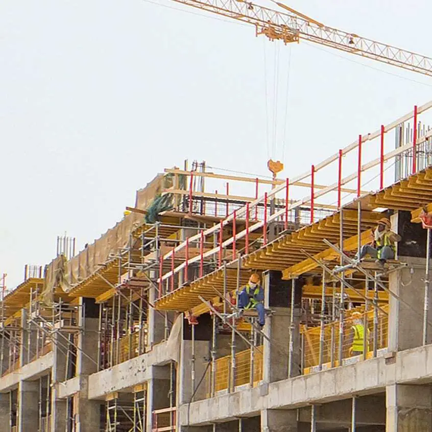
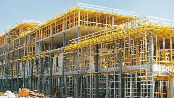
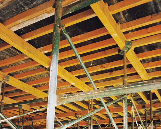
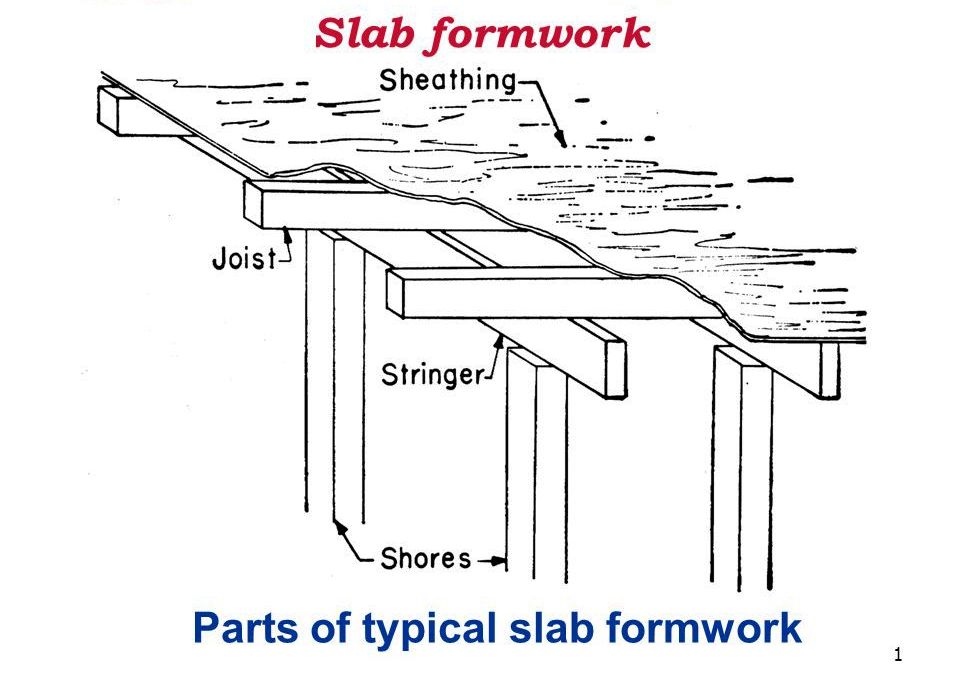
A typical formwork configuration for floor slabs is shown in the figure below;
Before construction commences, it is very important that the formwork be well-designed. The design effort required will be determined by the form’s size, complexity, height above the ground, and materials (considering reuses). In all cases, the strength and serviceability of the formwork should be considered in the design. Furthermore, the entire system’s stability and member buckling should be checked.
Formwork for reinforced concrete structures should be designed to safely handle all vertical and lateral loads that may be imposed until the concrete structure can take such loads. The weight of reinforcing steel, fresh concrete, the weight of the forms themselves, and numerous live loads exerted during the construction are all loads on the forms.
Furthermore, wind load can cause lateral forces that must be resisted by the formwork to avoid lateral failure. The formwork system or in-place structure with suitable strength for that purpose should carry vertical and lateral loads to the ground.
Loads and Pressures on Formworks
Unsymmetrical concrete pouring/placement, impact from machine-delivered concrete, uplift, and concentrated loads caused by keeping supplies on the freshly constructed slab must all be considered while designing the forms. There will rarely be precise knowledge about the loads that will be applied to the forms, therefore the designer must make certain safe assumptions that will hold true in most situations. The sections that follow are intended to assist the designer in establishing the loading on which to base form design for typical structural concrete situations.
Lateral Pressure of fresh Concrete on Formwork
The gravity load on a horizontal slab or beam formwork differs from the loads imposed by fresh concrete against wall or column formwork. The freshly placed concrete behaves like a fluid for a short time until the concrete begins to set, causing hydrostatic pressure to act laterally on the vertical forms.
Concrete pressure on formwork is primarily determined by several or all of the following factors:
- Rate of placing concrete in forms (R)
- The temperature of concrete (T)
- Weight or density of concrete (ρ)
- Cement type or blend used in the concrete.
- Method of consolidating the concrete.
- Method of placement of the concrete.
- Depth of placement.
- Height of form.
Lateral Pressure equations
The American Concrete Institute has spent a lot of time and effort researching and studying form design and construction techniques. The complete hydrostatic lateral pressure, as defined by the following equations, is the maximum pressure on formwork, according to ACI Committee (347).
p = ρgh (kPa) ——— (1)
The set characteristics of a concrete mixture should be understood, and the level of fluid concrete can be calculated using the rate of placement. When more than one placement of concrete is to be made, (h) should be taken as the complete height of the form or the distance between horizontal construction joints for columns or other forms that can be filled quickly before stiffening of the concrete occurs.
When working with mixtures using newly introduced admixtures that increase set time or increase slump characteristics, such as self-consolidating concrete, Eq. (1) should be used until the effect on formwork pressure is understood by measurement.
For concrete having a slump of 175 mm or less and placed with normal internal vibration to a depth of 1.2 m or less, formwork can be designed for a lateral pressure as follows:
For columns:
For determining pressure of concrete on formwork ACI 347 defines a column as a vertical structural member with no plan dimensions greater than 2m. For concrete with a slump (175 mm):
pmax = CwCc [7.2 + (785R/T + 17.8)] ——— (2)
With a minimum of 30 Cw kPa, but in no case greater than ρgh.
For walls: For determining pressure of concrete on formwork ACI 347 defines a wall as a vertical structural member with at least one plan dimension greater than 2m. Two equations are provided for wall form pressure:
(a) With a rate of placement of less than 2.1 m/hr and a placement height not exceeding 4.2 m :
pmax = CwCc [7.2 + (785R/T + 17.8)] ——— (3)
With a minimum of 30Cw kPa, but in no case greater than ρgh.
(b) with a placement rate less than 2.1 m/hr where placement height exceeds 4.2 m, and for all walls with a placement rate of 2.1 to 4.5 m/hr:
pmax = CwCc [7.2 + 1156/(T + 17.8) + 244/(T + 17.7)] ——— (4)
With a minimum of 30Cw kPa, but in no case greater than ρgh.
Where;
Cw = Unit weight coefficient which depends on the unit weight of the concrete
Cc = Chemistry coefficient which depends on the type of cementitious materials
Alternatively, a method based on appropriate experimental data can be used to determine the lateral pressure used for form design.
The unit weight coefficient Cw can be calculated using the Table below;
| Density of concrete | Unit weight coefficient (Cw ) |
| Less than 2240 kg/m3 | Cw = 0.5[1 + ρc/2320] but not less than 0.8 |
| 2240 – 2400 kg/m3 | Cw = 1.0 |
| More than 2400 kg/m3 | Cw = ρc /2320 |
The value of the chemistry coefficient Cc can be picked from the Table below;
| Type of cement | Chemistry Coefficient Cc |
| Types I, II, and III without retarders | 1.0 |
| Types I, II, and III with retarders | 1.2 |
| Other types or blends containing less than 70% slag or 40% fly ash without retarders | 1.2 |
| Other types or blends containing less than 70% slag or 40% fly ash with retarders | 1.4 |
| Other types or blends containing more than 70% slag or 40% fly ash | 1.4 |
In the UK, the formula for calculating the pressure on formworks according to CIRIA Report 108 is given by the equation below, which must not be greater than the hydrostatic pressure.
Pmax = [C1√R + C2K √(H1 – C1√R)]γ
Where:
Pmax = Maximum lateral pressure against formwork (kPa)
R = Rate of placement (m/h)
C1 = Coefficient for the size and shape of the formwork (1 for walls).
C2 = Coefficient for the constituent materials of the concrete (0.3 – 0.6).
γ = Specific weight of concrete (kN/m3).
H1 = Vertical form height (m).
K = Temperature coefficient K = (36/T + 16)2
Vertical loads on Formwork
In addition to lateral pressure, vertical loads are also imposed on formwork. Vertical loads consist of dead and live loads. The weight of formwork, the weight of the reinforcement and freshly placed concrete is dead load. The live load includes the weight of the workers, equipment, material storage, runways, and impact.
Vertical loads assumed for shoring and reshoring design for multistory construction should include all loads transmitted from the floors above as dictated by the proposed construction schedule.
The majority of all formwork involves concrete weighting 22 – 24 kN/m3. Minor variations in this weight are not significant, and for the majority of cases, 24 kN/m3 including the weight of reinforcing steel is commonly assumed for design. Formwork weights vary from as little as 0.15 to 0.7 kN/m2. When the formwork weight is small in relation to the weight of the concrete plus live load, it is frequently, neglected.
ACI committee 347 recommends that both vertical supports and horizontal framing components of formwork should be designed for a minimum live load of 2.4 kN/m2 of horizontal projection to provide for the weight of workmen, runways, screeds and other equipment. When motorized carts are used, the minimum should be 3.6 kN/m2. Regardless of slab thickness, the minimum design load for combined dead and live loads should not be less than 4.8 kN/m2 or 6.0 kN/m2 if motorized carts are used.
Horizontal loads on Formwork
Horizontal loads include the assumed value of load due to wind, dumping of concrete, inclined placement of concrete, cable tensions and equipment. The impact of wind increases with height. Horizontal loads should be not less than 1.5 kN/m of floor edge or 2% of total dead load on the form.
Bracing should be provided to withstand the side sway effects which occur when concrete is placed unsymmetrical on a slab form. Wall form bracing should be designed to meet the minimum wind load requirements of the local building code with adjustments for shorter recurrence intervals.
For wall forms exposed to the elements, the minimum wind design load should not be less than (0.72 kN/m2). Bracing for wall forms should be designed for a horizontal load of at least 1.5 kN/m of wall length, applied at the top. Wall forms of unusual height or exposure should be given special consideration.
Formwork Requirement for Suspended Slabs
In Nigeria, the standard given below works for normally proportioned reinforced concrete slabs.
Sheathing – 20 mm thick marine plywood
Joists – 200mm deep wooden H-beams spaced at 600 mm c/c
Stringers – 200mm deep wooden H-beams spaced at 1000 mm c/c
Shores – Steel props spaced at 1000 mm c/c
For low-cost construction, the following can be used;
Sheathing – 25 mm thick wooden planks
Joists – 2″ x 3″ wood (50 mm x 75 mm) spaced at 400mm c/c
Stringers – 2″ x 4″ wood (50 mm x 100 mm) spaced at 600 mm c/c
Shores – Bamboo wood spaced at 600 mm c/c
Now having known how to arrange formwork for floor slab, the next phase is to determine how to place your order of materials. We will use a typical example to show how it is done.
The first-floor plan of a building is shown below. We are to determine the formwork requirement of the floor slab. We will be neglecting the floor beams in this calculation.
On studying the drawing,
Length of longer side of building = 16.120 m
Length of shorter side of building = 12.530 m
Therefore, gross area of building = 201.9836 m2
Area of openings (lift and staircase) = 18.21 m2
Therefore net area of slab = 201.9836 – 18.21 = 183.7736 m2
Marine Plywood Requirement
Area of each marine plywood = 2.4m x 1.2m = 2.88 m2
Number of marine plywood required = 183.7736/2.88 = 63.8
Therefore, supply 64 pieces of (2.4m x 1.2m) marine plywood (no allowance for wastage)
If plank were to be used;
Area of one plank = 3.6m x 0.3m = 1.08 m2
Therefore, supply 183.7736/1.08 = 171 pcs of (1″ x 12″ x 12′ plank)
Floor Joist Requirement
Length of wooden H-beam = We normally have variety of 3.9 m or 2.9 m
Considering the longer side of the building;
Number of H-beam required per line = 16.12/3.9 = 4.13 No
We can therefore say, provide 4 No of 3.9m H-beam and 1 No of 2.9m H-beam per line (there will be projections though, and appropriate considerations should be made on site)
Spacing = 600mm
Therefore number of lines required = 12.53/0.6 + 1 = 22 lines
Hence provide;
3.9m H-beam = 4 x 22 = 88 pieces
2.9m H-beam = 1 x 22 = 22 pieces
If it were to be that 2″ x 3″ wood will be used;
Supply length of 2″ x 3″ wood in Nigeria = 3.6m
Number of 2″ x 3″ wood required per line = 16.12/3.6 = 4.47 pcs
At a spacing of 400 mm, we have 12.53/0.4 + 1 = 33 lines
Therefore number of 2″ x 3″ wood required for floor joists = 4.47 x 33 = 148 pieces
Stringer Requirement
We will also be using wooden H-beams for stringers. This will run parallel to the shorter side of the building;
Number of H-beam required per line = 12.53/3.9 = 3.21
We can therefore say, provide 3 No of 3.9m H-beam and 1 No of 2.9m H-beam per line
Spacing = 1000mm
Therefore number of lines required = 16.12/1.0 + 1 = 17 lines
Summarily provide;
3.9m H-beam = 3 x 17 = 51 pieces
2.9m H-beam = 1 x 17 = 17 pieces
Shoring Requirement
Steel acrow props will be used for the shoring;
Spacing = 1m c/c
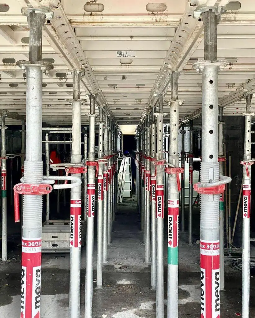
Number required on the longer side = 16.12/1 + 1 = 17 pcs
Number required on the shorter side = 12.53/1 + 1 = 14 pcs
Acrow props required = 17 x 14 = 238 pieces
Number of props required in the lift and staircase area
Length of lift area and staircase area = 5.055m (6 props)
Width of lift and staircase area = 3.60m (5 props)
Number of props that would have been in lift area = 5 x 6 = 30 pieces
Therefore, the total number of acrow props required = 238 – 30 = 208 pieces
Formwork summary for floor slab;
- Marine ply wood = 64 pieces
- 3.9m H-beam = 88 + 51 = 139 pieces
- 2.9m H-beam = 17 + 22 = 39 pieces
- Acrow Props = 208 pieces
Note that all these materials can be hired because they are very reusable. This is one of the advantages. For instance, marine plywood can be used 8 times before it gets damaged, and wooden H-beams (joists) are very durable for a long period of time provided they are well handled and protected from long exposure to moisture.
I hope you found this piece of information helpful. Thank you for visiting Structville today and God bless you. Kindly contact info@structville.com and find out how we can be of help to you.










Wonderful analysis….Thanks so much for sharing.
very useful & well explained. thanks for sharing.
Nice work, consideration of nails to be used need to be included
It was really informative
Nice analyses, I felt something is missing in your calculation the formwork that will carter for the thickness of the slab. A board running round the area of slab with slab thickness of either 100mm or 0.15mm depth depending on the spec.
Very nice, educational.
ONE THING I LOVE ABOUT THIS IS THE SIMPLICITY. EASY TO READ AND UNDERSTAND. KEEP IT UP
nice eduvation, but exsample doc. not yet
seems the bamboo method don’t require stringer right ?
Nice struggle ,,,,,Could you please send me at ishaq_614@yahoo.com
The article “Design and Calculation of Formwork Requirement of Slabs” provides a comprehensive guide for determining the necessary formwork materials for slab construction. The author’s detailed calculations and clear explanations make the process easy to understand and implement. Overall, this article is a valuable resource for construction professionals and students alike seeking to improve their understanding of slab formwork requirements.