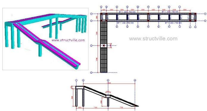
Pedestrian bridges (footbridges) are structures designed to enable human beings to cross over obstacles such as busy highways, water bodies, gullies, etc on foot. There are several variations of foot bridges based on structural configuration and materials. Modern footbridges are increasingly becoming elements of street beautification, with a view to sustainability and environmental friendliness.
In this article, a simple pedestrian bridge has been modelled on Staad Pro software, and the result of internal stresses due to crowd load on the bridge is presented.
Actions on Footbridges
The actions on footbridges are explicitly covered in section 5 of EN 1991-2. The load models presented in the code and their representative values (which include dynamic amplification effects) should be used for ultimate and serviceability limit state static calculations. However, ad hoc studies are required when vibration assessment based on specific dynamic analysis is necessary.
There are three mutually exclusive envisaged vertical load models for footbridges (5.3.1(2) EN 1991-2:2003);
(1) A uniformly distributed load representing the static effect of a dense crowd
(2) One concentrated load representing the effect of the maintenance load
(3) One or more mutually exclusive standard vehicles to be taken into account when maintenance or emergency vehicles are expected to cross the footbridge itself (not applicable in this article).
The effect of crowd action on a footbridge is represented by a uniformly distributed load, which depends on the loaded length of the footbridge. However, when a road bridge is supporting a footway, a UDL value of 5.0 kN/m2 is recommended by the code for that section. This value is synonymous with continuous dense crowd action, which is given by Load Model 4 of road bridges. However, when there is no such risk of dense crowd action, the load on the pedestrian bridge is given by;
qfk = 2.5 kN/m2 ≤ 120/(L + 30) ≤ 5.0 kN/m2
For local assessment, a concentrated load of 10 kN is considered to be acting on a square surface of sides 0.1 m. This load is not to be combined with other variable non-traffic loads.
For horizontal forces, a horizontal force acts simultaneously with the corresponding vertical load, whose characteristic value is equal to 10% of the total load corresponding to the uniformly distributed load. This horizontal force does not coexist with the concentrated load, and acts along the bridge deck axis at the pavement level on a square surface of sides 0.1 m. This force is usually sufficient to ensure the horizontal longitudinal stability of the bridge.
However, there are also non-traffic actions that are possible on footbridges, such as thermal action, wind action, snow action, indirect actions such as support settlement, etc. It is also important to consider accidental actions on the bridge, especially vehicle collisions on the substructure of the bridge. For stiff piers, EN 1991-2:2003 recommends a minimum force of 1000 kN in the direction of vehicle travel or 500 kN in the perpendicular direction. These collision forces are supposed to act at 1.25m above the level of the ground surface.
N/B: Vehicle collision on the piers is more common on footbridges than highway bridges. Therefore, it is highly recommended that the piers of the footbridge be protected using any reasonable and effective approach. Road restraint systems can be installed at a distance from the piers. Furthermore, the deck of the footbridge should be high enough to prevent collision or pose an obstruction to vehicles with a high frame.
Design Example
A pedestrian bridge with the following configuration is shown below;
The pedestrian bridge has been modelled on Staad Pro using the dimensions shown above.
For the sake of clarity, the cross-sectional dimensions of the members are as follows;
Main longitudinal girders – 400 x 750 mm
Transverse girders at the supports – 400 x 750 mm
Intermediate transverse girders – 250 x 450mm
All columns – 400 x 400 mm
Thickness of slab – 200 mm
The self-weight of the structure will be calculated automatically by Staad Pro. The pedestrian crowd action has been calculated as;
qfk = 120/(27 + 30) = 2.10 kN/m2 ≤ 2.5 kN/m2
But let us envisage that there is a possibility of continuous dense crowd action (e.g the pedestrian bridge at Ojota, Lagos, or lets say the pedestrian bridge will be located as Oshodi Bus Stop, Lagos). In this case, it is very reasonable to take qfk as 5.0 kN/m2
The total force due to UDL on the bridge can be taken as 5 kN/m2 x 2m x 27m = 270 kN
Therefore, an equivalent horizontal force that can be applied on the bridge deck is 27 kN
The images below show the internal stresses diagram due to crowd load;
The maximum moment at the intermediate supports of the main longitudinal beam due to the characteristic crowd load is 62.7 kNm.
The other internal forces diagrams due to crowd load alone are shown below;
So we are going to stop here for now. Remember that you have to consider other load cases and combinations in order to arrive at the design moment.
The modelling, analysis, and drawings you see on this post were produced by Ubani Obinna for Structville Integrated Services. We are creative, we think critically, we research, and we solve problems. You can trust us with yours, so feel free to contact us.
WhatsApp: +2347053638996
E-mail: ubani@structville.com


• It’s fantastic that you are getting ideas from this post as well
as from our discussion made at this place.
BIM Consulting
BIM Solutions
BIM Solutions in UK
Shop Drawings Preparation in UK
Fabrication Drawings preparation in UK
MEP F modelling in UK
Interference Analysis in UK
COBie adaptation in UK
Hello. I’m very happy seeing this. But please can I get a material on manual design of pedestrian bridge. Thank you sir